STATUS FUNCTION - This function shows the rotating display, current status of alarm (diagnostic) codes, capacity stages, operating modes, chilled water set point, all meas- ured system temperatures and pressures, superheat values, pressure switch positions, analog inputs, and switch inputs .

These subfunctions are defined on pages 37 and 38.

i

m(R oFita t i n g D i s p l a y )

(AlarmFis) - Alarms are messages that one or more faults have been detected. Each fault is assigned a code num- ber which is reported with the alarm. See Table 10 for code definitions. The codes indicate failures that cause the unit to shut down, terminate an option (such as reset) or result in the use of a default value as set point.

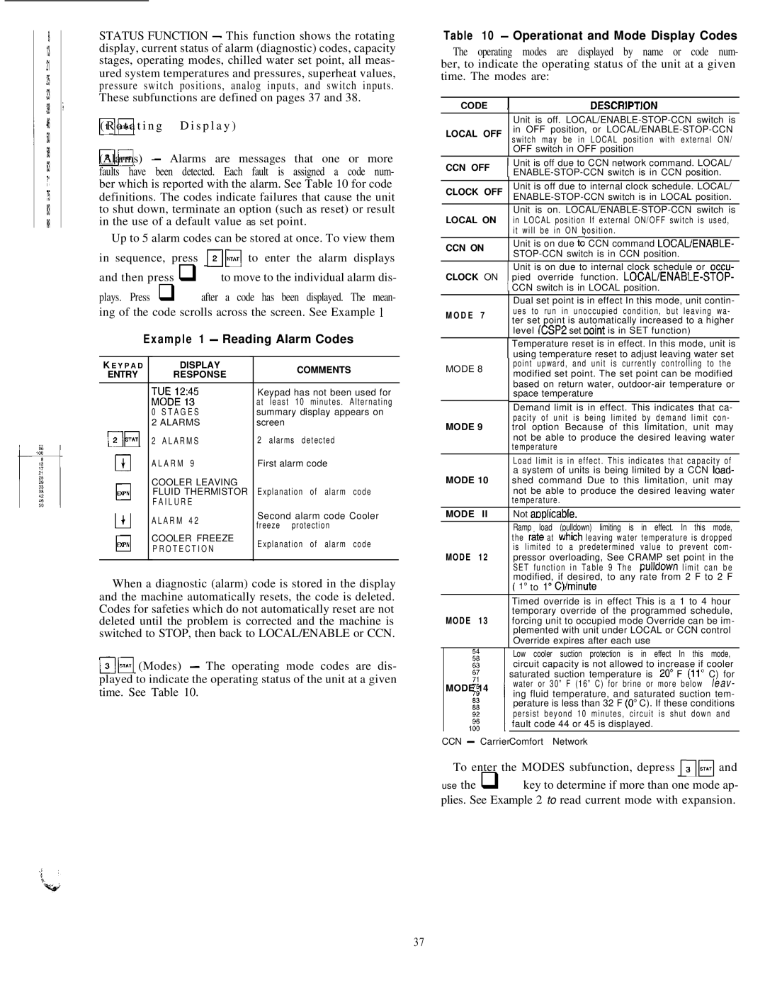
Up to 5 alarm codes can be stored at once. To view them

in sequence, press mm to enter the alarm displays and then press q to move to the individual alarm dis-

plays. Press q after a code has been displayed. The mean- ing of the code scrolls across the screen. See Example 1

Example 1 - Reading Alarm Codes

K E Y P A D

DISPLAY

COMMENTS


ENTRY

RESPONSE


‘MvoEo;2;;5

Keypad has not been used for


at least 10 minutes. Alternating


0 STAGES

summary display appears on


2 ALARMS

screen


p-jq

2 ALARMS

2 alarms detected


cl

ALARM 9

First alarm code


+


EXPH

COOLER LEAVING


FLUID THERMISTOR

Explanation of alarm

code

0

FAILURE


4

ALARM 42

Second alarm code Cooler

Ll


freeze protection


EXPN

COOLER FREEZE

Explanation of alarm

code

0

PROTECTION


When a diagnostic (alarm) code is stored in the display and the machine automatically resets, the code is deleted. Codes for safeties which do not automatically reset are not deleted until the problem is corrected and the machine is switched to STOP, then back to LOCAL/ENABLE or CCN.

mbi (Modes) - The operating mode codes are dis- played to indicate the operating status of the unit at a given time. See Table 10.

Table 10 - Operationat and Mode Display Codes

The operating modes are displayed by name or code num- ber, to indicate the operating status of the unit at a given time. The modes are:

CODE

1

DESCRlPTlON


Unit is off. LOCAL/ENABLE-STOP-CCN switch is

LOCAL OFF

in OFF position, or LOCAL/ENABLE-STOP-CCN


switch may be in LOCAL position with external ON/


OFF switch in OFF position

CCN OFF

Unit is off due to CCN network command. LOCAL/

ENABLE-STOP-CCN switch is in CCN position.


CLOCK OFF

Unit is off due to internal clock schedule. LOCAL/

ENABLE-STOP-CCN switch is in LOCAL position.


Unit is on. LOCAL/ENABLE-STOP-CCN switch is

LOCAL ON

in LOCAL position If external ON/OFF switch is used,


it will be in ON bosition.

CCN ON

Unit is on due to CCN command LOCAUENABLE-

STOP-CCN switch is in CCN position.


Unit is on due to internal clock schedule or occu-

CLOCK ON

pied override function. LOCALIENABLE-STOP-


CCN switch is in LOCAL position.


Dual set point is in effect In this mode, unit contin-

M O D E

7

ues to run in unoccupied condition, but leaving wa-

ter set point is automatically increased to a higher


level (CSP2 set Point is in SET function)


Temperature reset is in effect. In this mode, unit is


using temperature reset to adjust leaving water set

MODE 8

point upward, and unit is currently controlling to the

modified set point. The set point can be modified


based on return water, outdoor-air temperature or


space temperature


Demand limit is in effect. This indicates that ca-


pacity of unit is being limited by demand limit con-

MODE 9

trol option Because of this limitation, unit may


not be able to produce the desired leaving water


temperature


Load limit is in effect. This indicates that capacity of


a system of units is being limited by a CCN load-

MODE 10

shed command Due to this limitation, unit may


not be able to produce the desired leaving water


temperature.


MODE

II

Not aoalicable.I I


Ramp load (pulldown) limiting is in effect. In this mode,


the r&e at which leaving water temperature is dropped


is limited to a predetermined value to prevent com-

MODE

12

pressor overloading, See CRAMP set point in the


SET function in Table 9 The pulldown limit can be


modified, if desired, to any rate from 2 F to 2 F


( lo to lo Q/minute


Timed override is in effect This is a 1 to 4 hour


temporary override of the programmed schedule,

MODE

13

forcing unit to occupied mode Override can be im-


plemented with unit under LOCAL or CCN control


Override expires after each use


Low cooler suction protection is in effect In this mode,


circuit capacity is not allowed to increase if cooler


saturated suction temperature is 20” F (11” C) for

MODE


’water or 30” F

(16” C) for brine or more below l e a v -


ing fluid temperature, and saturated suction tem-

14perature is less than 32 F (0’ C). If these conditions persist beyond 10 minutes, circuit is shut down and fault code 44 or 45 is displayed.

CCN - CarrierComfort Network

To enter the MODES subfunction, depress MFI and use the q key to determine if more than one mode ap- plies. See Example 2 to read current mode with expansion.

37

Page 37
Image 37
Carrier 040-420 specifications Example 1 Reading Alarm Codes, Operationat and Mode Display Codes

040-420 specifications

The Carrier 040-420 is a highly regarded commercial HVAC unit specifically designed for efficient heating and cooling in medium- to large-sized buildings. Known for its reliability and advanced technology, this system is ideal for a variety of applications ranging from offices to industrial spaces.

One of the main features of the Carrier 040-420 is its energy efficiency. The unit utilizes advanced compressors and a high-efficiency heat exchanger, which work together to minimize energy consumption while maximizing performance. This is crucial in today’s energy-conscious environment, as businesses strive to reduce operational costs and their carbon footprint. The unit also boasts a high SEER (Seasonal Energy Efficiency Ratio) rating, making it an attractive option for those looking to lower their utility bills.

Equipped with advanced inverter-driven technology, the Carrier 040-420 allows for precise control of indoor climate conditions. This means that the system can adjust its output according to the actual cooling or heating demand of the space, resulting in enhanced comfort and reduced energy waste. The inverter technology also contributes to quieter operation, allowing for a more pleasant indoor environment.

Another feature that sets the Carrier 040-420 apart is its smart controls. The unit can be integrated with Carrier’s Building Automation Systems, enabling remote monitoring and management. This allows facility managers to optimize energy use and immediately respond to any performance issues. Additionally, the unit is compatible with various control interfaces, making it easy for users to adjust settings or schedule operations according to the building's occupancy patterns.

The robust design of the Carrier 040-420 ensures longevity and durability, even in harsh environmental conditions. Its weatherproof casing protects the internal components, enhancing the unit's performance and reliability over time. Maintenance is simplified with accessible design features, allowing technicians to conduct service checks and repairs without extensive downtime.

Overall, the Carrier 040-420 stands out as a modern HVAC solution that combines energy efficiency, advanced technologies, and user-friendly features. Its commitment to performance and sustainability makes it an ideal choice for businesses looking to enhance comfort while being mindful of their energy consumption. With its blend of innovation and reliability, the Carrier 040-420 continues to be a preferred option in the commercial HVAC market.