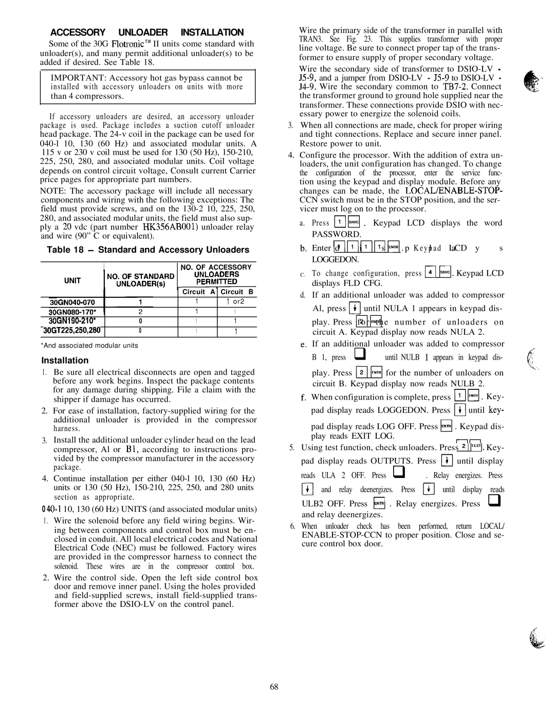
ACCESSORY UNLOADER INSTALLATION

Some of the 30G FlotronicT” II units come standard with unloader(s), and many permit additional unloader(s) to be added if desired. See Table 18.

IMPORTANT: Accessory hot gas bypass cannot be installed with accessory unloaders on units with more than 4 compressors.

If accessory unloaders are desired, an accessory unloader package is used. Package includes a suction cutoff unloader head package. The 24-v coil in the package can be used for 040-l 10, 130 (60 Hz) and associated modular units. A 115 v or 230 v coil must be used for 130 (50 Hz), 150-210, 225, 250, 280, and associated modular units. Coil voltage depends on control circuit voltage, Consult current Carrier price pages for appropriate part numbers.

NOTE: The accessory package will include all necessary

components and wiring with the following exceptions: The field must provide screws, and on the 130-2 10, 225, 250, 280, and associated modular units, the field must also sup- ply a 20 vdc (part number HK356ABOOl) unloader relay and wire (90” C or equivalent).

Table 18 - Standard and Accessory Unloaders

I


1NO. OF ACCESSORY


Circuit

A


Circuit B


1


1 or2


1


1

30GN190-210*

0


1


1


3OGT225,250,280

0


1


1


*And associated modular units

Installation

1 . Be sure all electrical disconnects are open and tagged before any work begins. Inspect the package contents for any damage during shipping. File a claim with the shipper if damage has occurred.

2.For ease of installation, factory-supplied wiring for the additional unloader is provided in the compressor harness.

3.

Install the additional unloader cylinder head on the lead


compressor, Al or El, according to instructions pro-


vided by the compressor manufacturer in the accessory


package.

4.

Continue installation per either 040-l 10, 130 (60 Hz)

1

units or 130 (50 Hz), 150-210, 225, 250, and 280 units

section as appropriate.


0 4-0-l 10, 130 (60 Hz) UNITS (and associated modular units)

1 . Wire the solenoid before any field wiring begins. Wir- ing between components and control box must be en- closed in conduit. All local electrical codes and National Electrical Code (NEC) must be followed. Factory wires are provided in the compressor harness to connect the solenoid. These wires are in the compressor control box.

2.Wire the control side. Open the left side control box door and remove inner panel. Using the holes provided and field-supplied screws, install field-supplied trans- former above the DSIO-LV on the control panel.

Wire the primary side of the transformer in parallel with TRAN3. See Fig. 23. This supplies transformer with proper line voltage. Be sure to connect proper tap of the trans- former to ensure supply of proper secondary voltage.

Wire the secondary side of transformer to DSIO-LV - J5-9, and a jumper from DSIO-LV - J5-9 to DSIO-LV - 54-9. Wire the secondary common to TB7-2. Connect the transformer ground to ground hole supplied near the transformer. These connections provide DSIO with nec- essary power to energize the solenoid coils.

3.When all connections are made, check for proper wiring and tight connections. Replace and secure inner panel. Restore power to unit.

4.Configure the processor. With the addition of extra un- loaders, the unit configuration has changed. To change the configuration of the processor, enter the service func- tion using the keypad and display module. Before any changes can be made, the LOCAL/ENABLE-STOP- CCN switch must be in the STOP position, and the ser- vicer must log on to the processor.

a.

Press pJl,,,l* Keypad

LCD displays the

word


PASSWORD.


b,

Enter md riim ms [;;;;;I

. p K e y pl a d LCDa y

s


LOGGEDON.


C.To change configuration, press m H. Keypad LCD displays FLD CFG.

d. If an additional unloader was added to compressor Al, press m until NULA 1 appears in keypad dis-

play. Press mf o r Fit h e n u m b e r o f u n l o a d e r s o n circuit A. Keypad display now reads NULA 2.

If an additional unloader was added to compressor B 1, press q until NULB 1 appears in keypad dis-

play. Press m bi for the number of unloaders on circuit B. Keypad display now reads NULB 2.

When configuration is complete, press mM. Key- pad display reads LOGGEDON. Press m until key-

pad display reads LOG OFF. Press H . Keypad dis-

play reads EXIT LOG.

III

5.Using test function, check unloaders. Press 12 1pEsTI. Key- pad display reads OUTPUTS. Press I)I until display

reads ULA 2 OFF. Press q . Relay energizes. Press a and relay deenergizes. Press Li_] until display reads

ULB2 OFF. Press H . Relay energizes. Press q and relay deenergizes.

6. When unloader check has been performed, return LOCAL/ ENABLE-STOP-CCN to proper position. Close and se- cure control box door.

68

Page 68
Image 68
Carrier 040-420 Standard and Accessory Unloaders, 1NO. of Accessory, Circuit Circuit B Or2 30GN190-210 3OGT225,250,280

040-420 specifications

The Carrier 040-420 is a highly regarded commercial HVAC unit specifically designed for efficient heating and cooling in medium- to large-sized buildings. Known for its reliability and advanced technology, this system is ideal for a variety of applications ranging from offices to industrial spaces.

One of the main features of the Carrier 040-420 is its energy efficiency. The unit utilizes advanced compressors and a high-efficiency heat exchanger, which work together to minimize energy consumption while maximizing performance. This is crucial in today’s energy-conscious environment, as businesses strive to reduce operational costs and their carbon footprint. The unit also boasts a high SEER (Seasonal Energy Efficiency Ratio) rating, making it an attractive option for those looking to lower their utility bills.

Equipped with advanced inverter-driven technology, the Carrier 040-420 allows for precise control of indoor climate conditions. This means that the system can adjust its output according to the actual cooling or heating demand of the space, resulting in enhanced comfort and reduced energy waste. The inverter technology also contributes to quieter operation, allowing for a more pleasant indoor environment.

Another feature that sets the Carrier 040-420 apart is its smart controls. The unit can be integrated with Carrier’s Building Automation Systems, enabling remote monitoring and management. This allows facility managers to optimize energy use and immediately respond to any performance issues. Additionally, the unit is compatible with various control interfaces, making it easy for users to adjust settings or schedule operations according to the building's occupancy patterns.

The robust design of the Carrier 040-420 ensures longevity and durability, even in harsh environmental conditions. Its weatherproof casing protects the internal components, enhancing the unit's performance and reliability over time. Maintenance is simplified with accessible design features, allowing technicians to conduct service checks and repairs without extensive downtime.

Overall, the Carrier 040-420 stands out as a modern HVAC solution that combines energy efficiency, advanced technologies, and user-friendly features. Its commitment to performance and sustainability makes it an ideal choice for businesses looking to enhance comfort while being mindful of their energy consumption. With its blend of innovation and reliability, the Carrier 040-420 continues to be a preferred option in the commercial HVAC market.