Carrier 040-420 specifications Alarm Codes

Models: 040-420

1 76
Download 76 pages 29.3 Kb
Page 49
Image 49
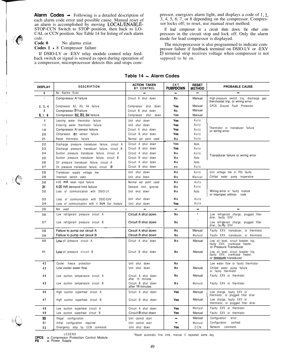
Table 14 - Alarm Codes

Alarm Codes - Following is a detailed description of each alarm code error and possible cause. Manual reset of an alarm is accomplished by moving LOCAWENABLE- STOP-CCN Switch to STOP position, then back to LO- CAL or CCN position. See Table 14 for listing of each alarm code.

Code 0 No alarms exist Codes 1 - 8 Compressor failure

If DSIO-LV or -EXV relay module control relay feed- back switch or signal is sensed as open during operation of a compressor, microprocessor detects this and stops com-

pressor, energizes alarm light, and displays a code of I, 2, 3, 4, 5, 6, 7, or 8 depending on the compressor. Compres- sor locks off; to reset, use manual reset method.

If lead compressor in a circuit shuts down, the other com- pressors in the circuit stop and lock off. Only the alarm mode for lead compressor is displayed.

The microprocessor is also programmed to indicate com- pressor failure if feedback terminal on DSIO-LV or -EXV 53 terminal strip receives voltage when compressor is not supposed to be on.

Table 14 - Alarm Codes


DISPLAY


D E S C R I P T I O N


ACTION TAKEN


C K T


PROBABLE CAUSE


B Y

C O N T R O L


PUMPDOWN


-


-


0


No Alarms

Exist


-


-


1


Compressor Al failure


Circuit

A

shut

down


No

Manual


High-pressure switch trip, discharge gas


thermostat trip, or wiring error


2, 3,

4


Compressor A2, A3, A4 failure


Compressor

shut

down


Yes

Manual


CPCS

Ground

Fault

Protection


5


Compressor Bl failure


Circuit

B

shut

down


No

Manual


6, 7,

8


Compressor B2; 83, 84 failure


Compressor

shut

down


Yes

Manual


9


Leaving

water

thermistor

failure


Unit

shut

down


Yes

Auto

I


1 0


Entering

water

thermistor failure


Unit

shut

down


Yes

Auto


Thermistor


or

transducer failure


1 9


Compressor Al sensor failure


Circuit

A

shut

down


Yes

Auto


or wiring error.


2 0


Compressor

Bl

sensor

failure


Circuit

B

shut

down


Yes

Auto


2 1


Reset

thermistor

failure


Normal

set

point

used


N o

Auto


2 2


Discharge pressure transducer failure, circuit A

Circuit

A

shut

down


Yes

Auto.


2 3


Discharge pressure transducer failure, circuit B

Circuit

B

shut

down


Yes

Auto


2 4


Suction pressure transducer failure, circuit A

Circuit

A

shut

down


N o

Auto


Transducer failure or wiring error


2 5


Suction pressure transducer failure, circuit B

Circuit

B

shut

down


N o

Auto.


2 6


Oil pressure transducer failure, circuit A

Circuit

A

shut

down


N o

Auto.


2 7


Oil pressure transducer failure, circuit

B

Circuit

B

shut

down


N O

Auto


2 8


Transducer

supply

voltage

low


Unit

shut

down


N o

Auto


Unit voltage low or PSI faulty


2 9


Interlock

switch


oaen


Unit

shut

down


N o

Manual


Chilled

water

pump

inoperative


3 0


4-20

mA

reset

input

failure


Normal

set

point

used


N o

Auto


31


4-20

mA

demand limit failure


Demand

limit

ignored


N o

Auto


3 2


Loss of communication with DSIO-LV

Unit

shut

down


N o

Auto.

I

Wiring error or

faulty

module


3 3


Loss of communication with DSIO-EXV

Unit

shut

down


N o

Auto

or improper address

code


3 4


Loss

of

communication with

4 In/4

Out module

Unit

shut

down


Yes

Auto


3 5


Not

used


-

-


-


I


-


*


3 6


Low refrigerant pressure circuit A


No


Low refrigerant charge, plugged filter


*


drier,

faulty

EXV


3 7


Low refrigerant pressure circuit B


No


Low refri erant charge, plugged filter


drier. fau I” tv EXV


~,


3


3 8


No

Manual


Faulty EXV, transducer, or thermistor


3 9


No

Manual


Faultv EXV, transducer, or thermistor.


4 0


oil

pressure


circuit

A


Circuit

A

shut

down


N o

Manual


Low oil level, circuit breaker trip,


faulty

EXV,

crankcase

heater,


or Pressure Transducer


4 1


oil

pressure


circuit

B


Circuit

B

shut

down


No

Manual


Low oil level, circuit breaker trip,


fautty

EXV,

crankcase

heater,


or oressure


transducer


4 2


Cooler

freeze

protection


Unit

shut


down


No


Low water flow or faulty thermistor


4 3


Low cooler water flow


Unit

shut


down


No

Manual


Chilled

water

pump failure


or faulty

thermistor


4 4


Low suction temperature circuit A


Circuit

A

shut

down


No

Manual


Faulty

EXV

or

thermistor


after

10

minutes


4 5


Low suction temperature circuit B


Circuit

B

shut

down


N o

Manual


Faulty

EXV

or

thermistor


afler 10 minutes


4 6


High suction superheat circuit A


Circuit

A

shut

down


Yes

Manual


Low charge, faulty EXV or


I thermistor, or plugged filter drier


4 7


High suction superheat circuit B


Circuit

B

shut

down


Yes

Manual


Low charge, faulty EXV or


thermistor, or plugged filter drier.


4 8


Low suction superheat circuit A


Circuit

A

shut

down


Yes

Manual


Faulty

EXV

or

thermistor


4 9


Low suction superheat circuit B


Circuit 6 shut down


Yes

Manual


Faultv

EXV

or

thermistor


50


Illegal

configuration


Unit

cannot

start


-

Manual


Configuration

error


5 1


Initial

configuration

required


Unit

cannot

start


-

Manual


Configuration

omitted


5 2


Emergency stop by CCN command


Unit

shut


down


Yes

C C N


Network

command.


LEGEND


*Reset


automatic first

time, manual if repeated same day


-Compressor Protection Control Module ES - Power Supply

49

Page 49
Image 49
Carrier 040-420 specifications Alarm Codes