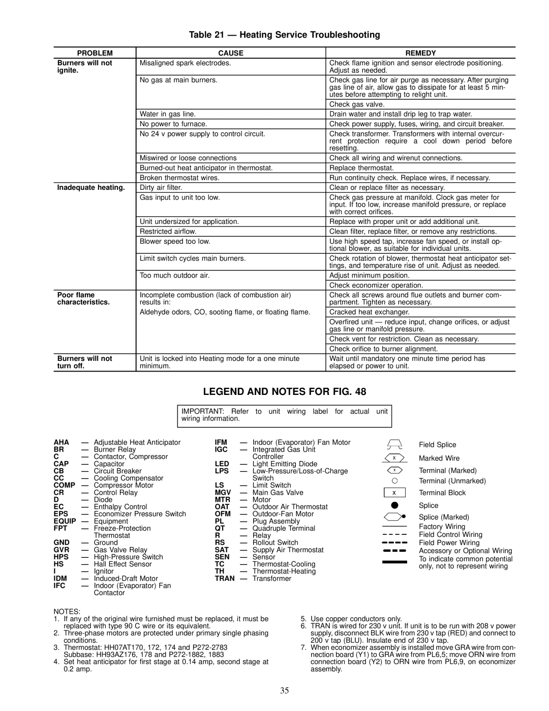
Table 21 Ð Heating Service Troubleshooting

PROBLEM

CAUSE

REMEDY

Burners will not

Misaligned spark electrodes.

Check ¯ame ignition and sensor electrode positioning.

ignite.


Adjust as needed.


No gas at main burners.

Check gas line for air purge as necessary. After purging


gas line of air, allow gas to dissipate for at least 5 min-


utes before attempting to relight unit.


Check gas valve.


Water in gas line.

Drain water and install drip leg to trap water.


No power to furnace.

Check power supply, fuses, wiring, and circuit breaker.


No 24 v power supply to control circuit.

Check transformer. Transformers with internal overcur-


rent protection require a cool down period before


resetting.


Miswired or loose connections

Check all wiring and wirenut connections.


Burned-out heat anticipator in thermostat.

Replace thermostat.


Broken thermostat wires.

Run continuity check. Replace wires, if necessary.

Inadequate heating.

Dirty air ®lter.

Clean or replace ®lter as necessary.


Gas input to unit too low.

Check gas pressure at manifold. Clock gas meter for


input. If too low, increase manifold pressure, or replace


with correct ori®ces.


Unit undersized for application.

Replace with proper unit or add additional unit.


Restricted air¯ow.

Clean ®lter, replace ®lter, or remove any restrictions.


Blower speed too low.

Use high speed tap, increase fan speed, or install op-


tional blower, as suitable for individual units.


Limit switch cycles main burners.

Check rotation of blower, thermostat heat anticipator set-


tings, and temperature rise of unit. Adjust as needed.


Too much outdoor air.

Adjust minimum position.


Check economizer operation.

Poor ¯ame

Incomplete combustion (lack of combustion air)

Check all screws around ¯ue outlets and burner com-

characteristics.

results in:

partment. Tighten as necessary.


Aldehyde odors, CO, sooting ¯ame, or ¯oating ¯ame.

Cracked heat exchanger.


Over®red unit Ð reduce input, change ori®ces, or adjust


gas line or manifold pressure.


Check vent for restriction. Clean as necessary.


Check ori®ce to burner alignment.

Burners will not

Unit is locked into Heating mode for a one minute

Wait until mandatory one minute time period has

turn off.

minimum.

elapsed or power to unit.

LEGEND AND NOTES FOR FIG. 48


IMPORTANT:

Refer to unit wiring label for actual

unit


wiring information.


AHA

Ð Adjustable Heat Anticipator

IFM

Ð Indoor (Evaporator) Fan Motor


Field Splice

BR

Ð Burner Relay

IGC

Ð Integrated Gas Unit


C

Ð Contactor, Compressor

LED

Controller


Marked Wire

CAP

Ð Capacitor

Ð Light Emitting Diode


Terminal (Marked)

CB

Ð Circuit Breaker

LPS

Ð Low-Pressure/Loss-of-Charge


CC

Ð Cooling Compensator


Switch


Terminal (Unmarked)

COMP

Ð Compressor Motor

LS

Ð Limit Switch


CR

Ð Control Relay

MGV

Ð Main Gas Valve


Terminal Block

D

Ð Diode

MTR

Ð Motor


Splice

EC

Ð Enthalpy Control

OAT

Ð Outdoor Air Thermostat


EPS

Ð Economizer Pressure Switch

OFM

Ð Outdoor-Fan Motor


Splice (Marked)

EQUIP

Ð Equipment

PL

Ð Plug Assembly


Factory Wiring

FPT

Ð Freeze-Protection

QT

Ð Quadruple Terminal


Thermostat

R

Ð Relay


Field Control Wiring

GND

Ð Ground

RS

Ð Rollout Switch


Field Power Wiring

GVR

Ð Gas Valve Relay

SAT

Ð Supply Air Thermostat


Accessory or Optional Wiring

HPS

Ð High-Pressure Switch

SEN

Ð Sensor


To indicate common potential

HS

Ð Hall Effect Sensor

TC

Ð Thermostat-Cooling


only, not to represent wiring

I

Ð Ignitor

TH

Ð Thermostat-Heating


IDM

Ð Induced-Draft Motor

TRAN Ð Transformer


IFC

Ð Indoor (Evaporator) Fan


Contactor


NOTES:

1.If any of the original wire furnished must be replaced, it must be replaced with type 90 C wire or its equivalent.

2.Three-phase motors are protected under primary single phasing conditions.

3.Thermostat: HH07AT170, 172, 174 and P272-2783

Subbase: HH93AZ176, 178 and P272-1882, 1883

4.Set heat anticipator for ®rst stage at 0.14 amp, second stage at 0.2 amp.

5.Use copper conductors only.

6.TRAN is wired for 230 v unit. If unit is to be run with 208 v power supply, disconnect BLK wire from 230 v tap (RED) and connect to 200 v tap (BLU). Insulate end of 230 v tap.

7.When economizer assembly is installed move GRA wire from con- nection board (Y1) to GRA wire from PL6,5; move ORN wire from connection board (Y2) to ORN wire from PL6,9, on economizer assembly.

35

Page 35
Image 35
Carrier 48TJF008-012, 48TJE008-014, 48TJD008-014 installation instructions Heating Service Troubleshooting

48TJF008-012, 48TJD008-014, 48TJE008-014 specifications

Carrier's 48TJD008-014, 48TJE008-014, and 48TJF008-012 series are high-performance packaged rooftop units engineered to meet the heating, ventilation, and air conditioning (HVAC) needs of commercial and industrial applications. These units are renowned for their reliability, energy efficiency, and advanced technologies, making them a popular choice among facility managers and HVAC professionals.

One of the standout features of these Carrier units is their robust construction. Designed to withstand diverse environmental conditions, these units come with durable cabinets that are resistant to corrosion and UV degradation. This durability extends the product lifespan and reduces maintenance needs, providing long-term savings for facility operators.

The series includes models ranging from 8 to 14 tons, catering to a variety of space requirements. Each unit is equipped with a high-efficiency scroll compressor that enhances performance while minimizing energy consumption. This compressor technology guarantees quieter operation, reduced vibrations, and exceptional reliability, which are critical factors in commercial settings.

Energy efficiency is a hallmark of the 48TJD, 48TJE, and 48TJF series. These units come with high Seasonal Energy Efficiency Ratios (SEER) and Energy Efficiency Ratios (EER), which result in lower energy bills and a reduced carbon footprint. The incorporation of advanced digital controls allows for precise temperature management and integration with building management systems, ensuring optimal performance throughout the year.

In terms of comfort features, the Carrier series utilizes variable-speed technology, enabling the fan to adjust its speed according to the load requirements. This results in more consistent temperature control and enhanced indoor air quality. The units also include options for enhanced filtration systems, which can accommodate various filter types, ensuring the removal of airborne particles and allergens.

Installation is simplified with these packaged rooftop units. Their compact design fits well on rooftops or in limited spaces, and they come with factory-installed components, which streamline the setup process. Additionally, the units feature easy access panels for maintenance, allowing technicians to conduct service with minimal disruption to operations.

Finally, Carrier's dedication to innovation is evident in the incorporation of smart technologies within these units. Integrated diagnostics and monitoring systems provide real-time performance data, enabling proactive maintenance and reducing the likelihood of unexpected breakdowns.

In summary, Carrier's 48TJD008-014, 48TJE008-014, and 48TJF008-012 rooftop units are engineered for efficiency, reliability, and comfort. With their durable construction, advanced compressor technology, energy efficiency, comfort features, and ease of installation, these units are ideal for meeting the demanding HVAC needs of commercial spaces.