FIELD CONTROL WIRING — Install a
NOTE: If using a Carrier electronic thermostat, set the thermo- stat configuration for
Route the thermostat cable or equivalent single leads of colored wire from the subbase terminals to the
NOTE: For wire runs up to 50 ft, use no. 18 AWG (American Wire Gage) insulated wire (35 C minimum). For 51 to 75 ft, use no. 16 AWG insulated wire (35 C minimum). For over 75 ft, use no. 14 AWG insulated wire (35 C minimum). All wire larger than no. 18 AWG cannot be directly connected to the thermostat and will require a junction box and splice at the thermostat.
1.If the unit is mounted on the roof curb and the accessory
2.Pass control wires through the hole provided on the unit (see connection D in Connection Sizes table in Fig. 6).
3.Feed wire through the raceway built into the corner post to the
4.Connect the thermostat wires to the screw terminals of the
NOTE: If the unit is mounted on a roof curb and electrical power will be run up
DEFROST BOARD — The defrost board timer cycle is set to 30 minutes. To change the cycle time, turn off power to the unit and install lockout tag. Remove the wire from defrost board connected to the 30 minute
HEAT ANTICIPATOR SETTINGS — For units with electric heat, set heat anticipator settings as shown in Table 4.
Step 6 — Adjust Factory-Installed Options
DISCONNECT SWITCH — The optional disconnect switch is
| CONTROL | THERMOSTAT CONTROL | |
CONNECTION | CONNECTION | ||
| BOARD |
| BOARD |
R | 24 VAC | R | R |
G | RMTOCC | Y1 | Y1 |
| CMPSAFE | Y2 | Y2 |
Y2 | FSD | W1 | W1 |
W1 | SFS | W2 | W2 |
| NOT USED | G | G |
C | C | C | C |
X | X | X |
|
Fig. 8B — Low Voltage Connections (Units with PremierLink™ Controls)
DISCONNECT
BOARD
COOL STAGE 1 | Y1/W2 |
FAN | G |
HEAT STAGE 1 | W/W1 |
COOL STAGE 2 | Y/Y2 |
HEAT STAGE 2 | O/W2 |
24 VAC HOT | R |
24 VAC COM | C |
N/A |
|
OUTDOOR AIR | S1 |
SENSOR | S2 |
R
G
Y1
Y2
W1
W2
C
IPD/X
WIRE CONNECTIONS TO
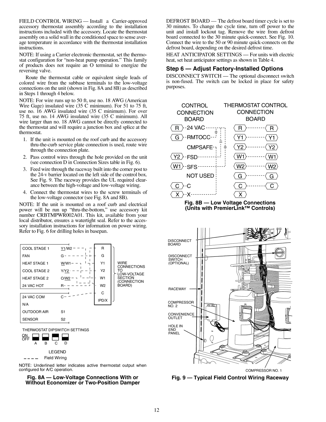
DISCONNECT SWITCH (OPTIONAL)
RACEWAY
COMPRESSOR
NO. 2
CONVENIENCE OUTLET ![]()
THERMOSTAT DIPSWITCH SETTINGS
ON
OFF
A B C D
LEGEND
Field Wiring
NOTE: Underlined letter indicates active thermostat output when configured for A/C operation.
Fig. 8A — Low-Voltage Connections With or Without Economizer or Two-Position Damper
HOLE IN
END
PANEL
COMPRESSOR NO. 1
Fig. 9 — Typical Field Control Wiring Raceway
12