ECONOMI$ER IV STANDARD SENSORS
Outdoor Air Temperature (OAT) Sensor — The outdoor air temperature sensor (HH57AC074) is a 10 to 20 mA device used to measure the
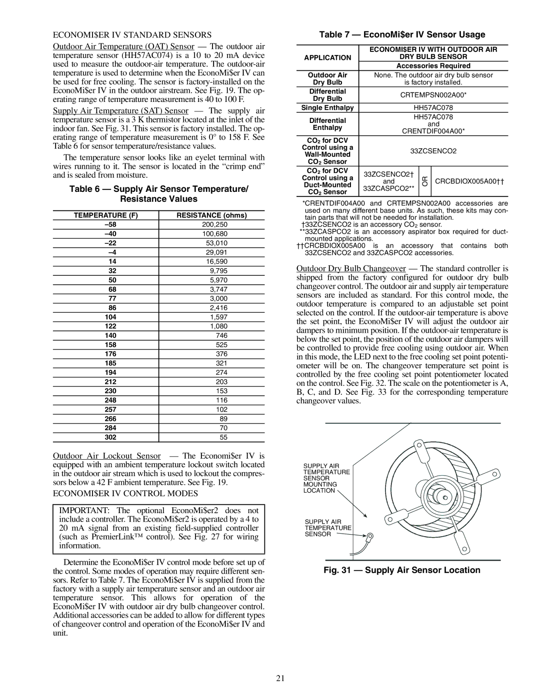
Supply Air Temperature (SAT) Sensor — The supply air temperature sensor is a 3 K thermistor located at the inlet of the indoor fan. See Fig. 31. This sensor is factory installed. The op- erating range of temperature measurement is 0° to 158 F. See Table 6 for sensor temperature/resistance values.
The temperature sensor looks like an eyelet terminal with wires running to it. The sensor is located in the “crimp end” and is sealed from moisture.
Table 6 — Supply Air Sensor Temperature/
Resistance Values
TEMPERATURE (F) | RESISTANCE (ohms) |
200,250 | |
100,680 | |
53,010 | |
29,091 | |
14 | 16,590 |
32 | 9,795 |
50 | 5,970 |
68 | 3,747 |
77 | 3,000 |
86 | 2,416 |
104 | 1,597 |
122 | 1,080 |
140 | 746 |
158 | 525 |
176 | 376 |
185 | 321 |
194 | 274 |
212 | 203 |
230 | 153 |
248 | 116 |
257 | 102 |
266 | 89 |
284 | 70 |
302 | 55 |
Outdoor Air Lockout Sensor — The Economi$er IV is equipped with an ambient temperature lockout switch located in the outdoor air stream which is used to lockout the compres- sors below a 42 F ambient temperature. See Fig. 19.
ECONOMI$ER IV CONTROL MODES
IMPORTANT: The optional EconoMi$er2 does not include a controller. The EconoMi$er2 is operated by a 4 to 20 mA signal from an existing
Determine the EconoMi$er IV control mode before set up of the control. Some modes of operation may require different sen- sors. Refer to Table 7. The EconoMi$er IV is supplied from the factory with a supply air temperature sensor and an outdoor air temperature sensor. This allows for operation of the EconoMi$er IV with outdoor air dry bulb changeover control. Additional accessories can be added to allow for different types of changeover control and operation of the EconoMi$er IV and unit.
Table 7 — EconoMi$er IV Sensor Usage
| ECONOMI$ER IV WITH OUTDOOR AIR | ||||
APPLICATION |
| DRY BULB SENSOR | |||
|
| Accessories Required | |||
Outdoor Air | None. The outdoor air dry bulb sensor | ||||
Dry Bulb |
| is factory installed. | |||
Differential |
| CRTEMPSN002A00* | |||
Dry Bulb |
| ||||
|
|
|
|
| |
Single Enthalpy |
| HH57AC078 | |||
Differential |
| HH57AC078 | |||
|
|
| and | ||
Enthalpy |
|
|
| ||
| CRENTDIF004A00* | ||||
|
| ||||
CO2 for DCV |
|
|
|
|
|
Control using a |
| 33ZCSENCO2 | |||
| |||||
|
|
|
|
| |
CO2 Sensor |
|
|
|
|
|
CO2 for DCV | 33ZCSENCO2† |
|
|
| |
Control using a | OR |
| CRCBDIOX005A00†† | ||
and |
|
| |||
|
| ||||
33ZCASPCO2** |
|
|
| ||
CO2 Sensor |
|
|
| ||
|
|
|
|
| |
*CRENTDIF004A00 and CRTEMPSN002A00 accessories are used on many different base units. As such, these kits may con- tain parts that will not be needed for installation.
†33ZCSENCO2 is an accessory CO2 sensor.
**33ZCASPCO2 is an accessory aspirator box required for duct- mounted applications.
††CRCBDIOX005A00 is an accessory that contains both 33ZCSENCO2 and 33ZCASPCO2 accessories.
Outdoor Dry Bulb Changeover — The standard controller is shipped from the factory configured for outdoor dry bulb changeover control. The outdoor air and supply air temperature sensors are included as standard. For this control mode, the outdoor temperature is compared to an adjustable set point selected on the control. If the
SUPPLY AIR
TEMPERATURE
SENSOR
MOUNTING
LOCATION
SUPPLY AIR
TEMPERATURE
SENSOR
Fig. 31 — Supply Air Sensor Location
21