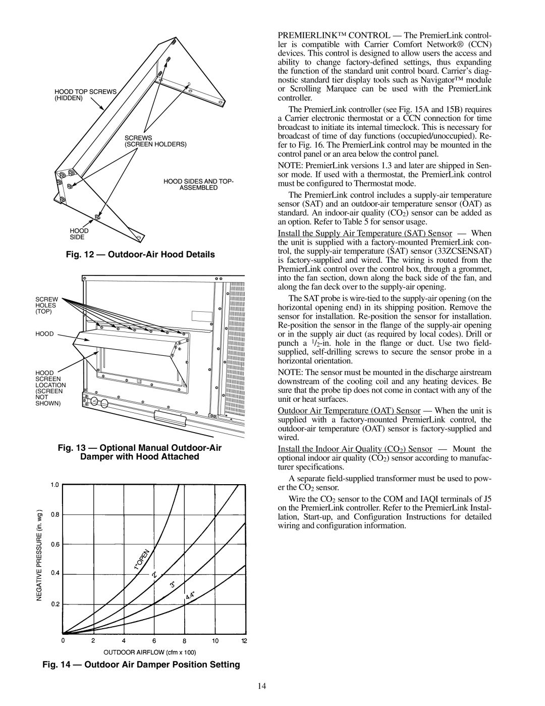
Fig. 12 — Outdoor-Air Hood Details
SCREW HOLES (TOP)
HOOD
HOOD SCREEN LOCATION (SCREEN NOT SHOWN)
Fig. 13 — Optional Manual Outdoor-Air
Damper with Hood Attached
Fig. 14 — Outdoor Air Damper Position Setting
PREMIERLINK™ CONTROL — The PremierLink control- ler is compatible with Carrier Comfort Network® (CCN) devices. This control is designed to allow users the access and ability to change
The PremierLink controller (see Fig. 15A and 15B) requires a Carrier electronic thermostat or a CCN connection for time broadcast to initiate its internal timeclock. This is necessary for broadcast of time of day functions (occupied/unoccupied). Re- fer to Fig. 16. The PremierLink control may be mounted in the control panel or an area below the control panel.
NOTE: PremierLink versions 1.3 and later are shipped in Sen- sor mode. If used with a thermostat, the PremierLink control must be configured to Thermostat mode.
The PremierLink control includes a
Install the Supply Air Temperature (SAT) Sensor — When the unit is supplied with a
The SAT probe is
NOTE: The sensor must be mounted in the discharge airstream downstream of the cooling coil and any heating devices. Be sure that the probe tip does not come in contact with any of the unit or heat surfaces.
Outdoor Air Temperature (OAT) Sensor — When the unit is supplied with a
Install the Indoor Air Quality (CO2) Sensor — Mount the optional indoor air quality (CO2) sensor according to manufac- turer specifications.
A separate
Wire the CO2 sensor to the COM and IAQI terminals of J5 on the PremierLink controller. Refer to the PremierLink Instal- lation,
14