Table 29 — EconoMi$er IV Input/Output Logic
| INPUTS |
|
|
|
|
| OUTPUTS |
| |
Demand Control | Enthalpy* |
|
|
| Compressor | N Terminal† | |||
|
| Y1 | Y2 | Stage | Stage | Occupied | Unoccupied | ||
Ventilation (DCV) | Outdoor | Return | |||||||
|
| 1 | 2 | Damper | |||||
|
|
|
|
| |||||
Below set | High | Low | On | On | On | On | Minimum position | Closed | |
(DCV LED Off) | (Free Cooling LED Off) |
| On | Off | On | Off |
|
| |
|
|
|
|
| |||||
|
|
| Off | Off | Off | Off |
|
| |
| Low | High | On | On | On | Off | Modulating** (between min. | Modulating** (between | |
| (Free Cooling LED On) |
| On | Off | Off | Off | position and | closed and | |
|
|
|
|
| |||||
|
|
| Off | Off | Off | Off | Minimum position | Closed | |
Above set | High | Low | On | On | On | On | Modulating†† (between min. | Modulating†† (between | |
(DCV LED On) | (Free Cooling LED Off) |
| On | Off | On | Off | position and DCV maximum) | closed and DCV | |
|
|
|
| maximum) | |||||
|
|
| Off | Off | Off | Off |
| ||
|
|
|
|
| |||||
| Low | High | On | On | On | Off | Modulating*** | Modulating††† | |
| (Free Cooling LED On) |
| On | Off | Off | Off |
|
| |
|
|
|
|
| |||||
|
|
| Off | Off | Off | Off |
|
| |
*For single enthalpy control, the module compares outdoor enthalpy to the ABCD set point.
†Power at N terminal determines Occupied/Unoccupied setting: 24 vac (Occupied), no power (Unoccupied).
**Modulation is based on the
***Modulation is based on the greater of DCV and
†††Modulation is based on the greater of DCV and
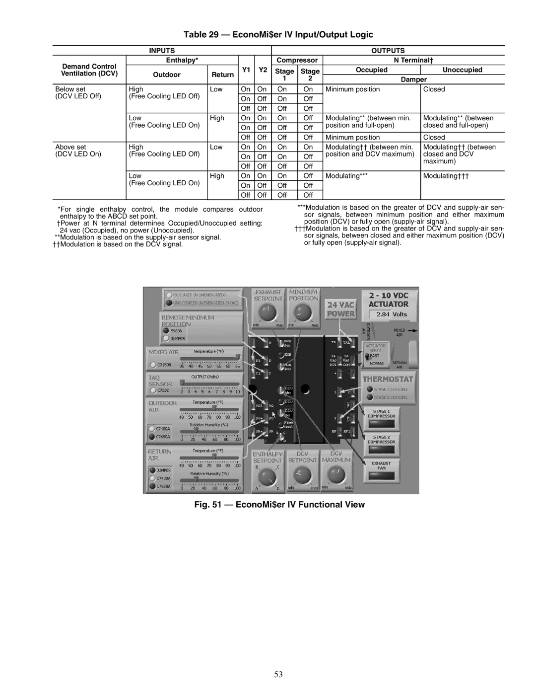
Fig. 51 — EconoMi$er IV Functional View
53