Fig. 32 — EconoMi$er IV Controller Potentiometer
and LED Locations
19
| 18 | LED ON |
|
|
|
| D |
|
|
| |
| 17 |
|
|
| |
|
|
|
|
| |
| 16 | LED OFF | LED ON |
|
|
| C |
|
| ||
| 15 |
|
|
| |
|
|
|
|
| |
mA | 14 |
| LED OFF | LED ON |
|
|
| B |
| ||
| 13 |
|
|
| |
|
|
|
|
| |
| 12 |
|
| LED OFF | LED ON |
|
|
|
| A | |
| 11 |
|
|
|
Differential Enthalpy Control — For differential enthalpy control, the EconoMi$er IV controller uses two enthalpy sen- sors (HH57AC078 and CRENTDIF004A00), one in the out- side air and one in the return air duct. The EconoMi$er IV controller compares the outdoor air enthalpy to the return air enthalpy to determine EconoMi$er IV use. The controller selects the lower enthalpy air (return or outdoor) for cooling. For example, when the outdoor air has a lower enthalpy than the return air, the EconoMi$er IV opens to bring in outdoor air for free cooling.
Replace the standard outside air dry bulb temperature sen- sor with the accessory enthalpy sensor in the same mounting location. See Fig. 19. Mount the return air enthalpy sensor in the return air duct. See Fig. 34. Wiring is provided in the EconoMi$er IV wiring harness. See Fig. 26. The outdoor en- thalpy changeover set point is set with the outdoor enthalpy set point potentiometer on the EconoMi$er IV controller. When using this mode of changeover control, turn the enthalpy set- point potentiometer fully clockwise to the D setting.
Indoor Air Quality (IAQ) Sensor Input — The IAQ input can be used for demand control ventilation control based on the level of CO2 measured in the space or return air duct.
Mount the accessory IAQ sensor according to manufacturer specifications. The IAQ sensor should be wired to the AQ and AQ1 terminals of the controller. Adjust the DCV potentiome- ters to correspond to the DCV voltage output of the indoor air quality sensor at the
If a separate
10 |
|
|
|
|
|
|
|
|
| LED OFF |
| |
|
|
|
|
|
|
|
|
|
|
| ||
9 |
|
|
|
|
|
|
|
|
|
|
| 100 |
40 | 45 | 50 | 55 | 60 | 65 | 70 | 75 | 80 | 85 | 90 | 95 | |
|
|
|
| DEGREES FAHRENHEIT |
|
|
|
| ||||
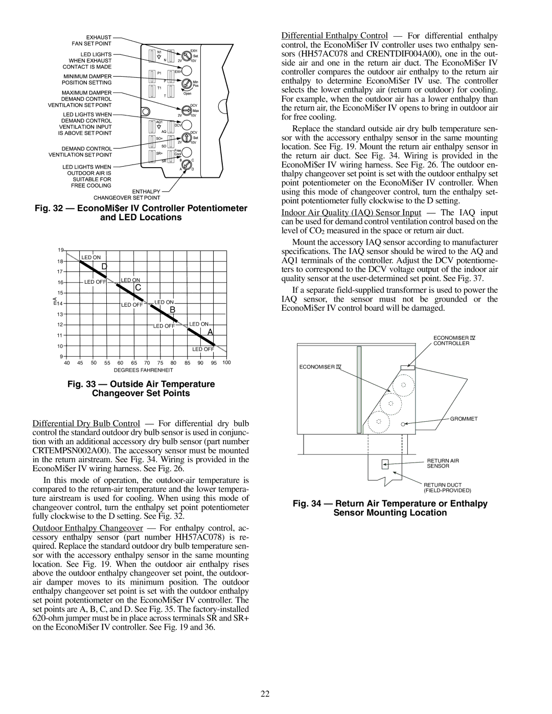
Fig. 33 — Outside Air Temperature
Changeover Set Points
Differential Dry Bulb Control — For differential dry bulb control the standard outdoor dry bulb sensor is used in conjunc- tion with an additional accessory dry bulb sensor (part number CRTEMPSN002A00). The accessory sensor must be mounted in the return airstream. See Fig. 34. Wiring is provided in the EconoMi$er IV wiring harness. See Fig. 26.
In this mode of operation, the
ECONOMI$ER IV
ECONOMI$ER IV
CONTROLLER
![]() GROMMET
GROMMET
RETURN AIR
SENSOR
RETURN DUCT
changeover control, turn the enthalpy set point potentiometer fully clockwise to the D setting. See Fig. 32.
Outdoor Enthalpy Changeover — For enthalpy control, ac- cessory enthalpy sensor (part number HH57AC078) is re- quired. Replace the standard outdoor dry bulb temperature sen- sor with the accessory enthalpy sensor in the same mounting location. See Fig. 19. When the outdoor air enthalpy rises above the outdoor enthalpy changeover set point, the outdoor- air damper moves to its minimum position. The outdoor enthalpy changeover set point is set with the outdoor enthalpy set point potentiometer on the EconoMi$er IV controller. The set points are A, B, C, and D. See Fig. 35. The
Fig. 34 — Return Air Temperature or Enthalpy
Sensor Mounting Location
22