Step 5 — Make Electrical Connections
Unit cabinet must have an uninterrupted, unbroken electri- cal ground to minimize the possibility of personal injury if an electrical fault should occur. This ground may consist of electrical wire connected to unit ground lug in control com- partment, or conduit approved for electrical ground when installed in accordance with NEC (National Electrical Code) ANSI (American National Standards Institute)/ NFPA (National Fire Protection Association) 70 latest year and local electrical codes. Failure to follow this warning could result in the installer being liable for personal injury of others.
FIELD POWER SUPPLY — All units except
Refer to the unit label diagram for additional information. Pigtails are provided for field wire connections. Use factory- supplied splices or a UL (Underwriters’ Laboratories) approved copper/aluminum connector.
When installing units, provide a disconnect per the NEC.
All field wiring must comply with the NEC and local re- quirements. In Canada, electrical connections must be made in accordance with CSA (Canadian Standards Association) C22.1 Canadian Electrical Code Part One.
Install field wiring as follows:
1.Install conduit through the side panel openings. For units without electric heat, install conduit between the discon- nect and control box.
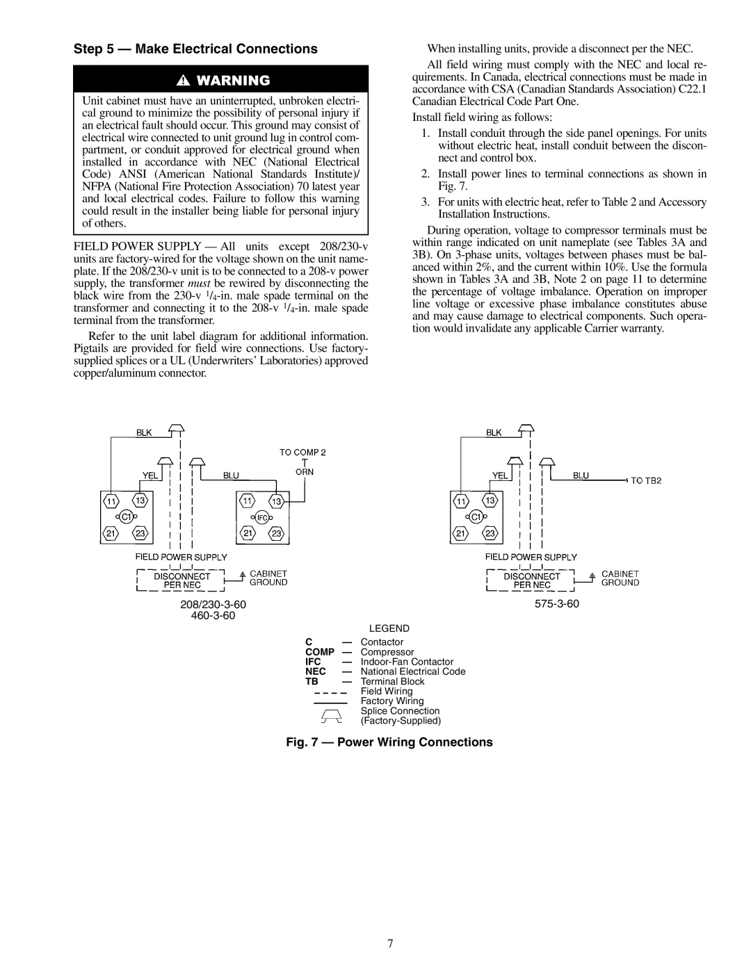
2.Install power lines to terminal connections as shown in Fig. 7.
3.For units with electric heat, refer to Table 2 and Accessory Installation Instructions.
During operation, voltage to compressor terminals must be within range indicated on unit nameplate (see Tables 3A and 3B). On
208/230-3-60 575-3-60 460-3-60
LEGEND
C— Contactor COMP — Compressor
IFC | — | |
NEC | — | National Electrical Code |
TB | — | Terminal Block |
|
| Field Wiring |
|
| Factory Wiring |
|
| Splice Connection |
|
|
Fig. 7 — Power Wiring Connections
7