58HDV
8.For horizontal installations, line contact is permissible only between lines formed by intersection of back and two sides of furnace jacket, and building joists, studs or framing.
9.Residential garage installations require:
SBurners and ignition sources installed at least 18″ (457.2mm) above the floor.
SLocated or physically protected from possible damage by a vehicle.
10.Local codes may require a drain pan under the entire furnace and condensate trap when the furnace is installed in attic application.
This furnace may be used for construction heat provided that all the following conditions are met:
SThe furnace is permanently installed with all electrical wiring, piping, venting and ducting installed according to these installation instructions. A return air duct is provided, sealed to the furnace casing, and terminated outside the space containing the furnace. This prevents a negative pressure condition as
created by the circulating air blower, causing a flame rollout and/or drawing combustion products into the structure.
SThe furnace is controlled by a thermostat. It may not be “hot wired” to provide heat continuously to the structure without thermostatic control.
SClean outside air is provided for combustion. This is to minimize the corrosive effects of adhesives, sealers and other construction materials. It also prevents the entrainment of drywall dust into combustion air, which can cause fouling and plugging of furnace components.
SThe temperature of the return air to the furnace is maintained
between 55° F (13° C) and 80° F (27° C) , with no evening setback or shutdown. The use of the furnace while the structure is under construction is deemed to be intermittent operation per our installation instructions.
SThe air temperature rise is within the rated rise range on the furnace rating plate, and the firing rate has been set to the rating plate value.
SThe filters used to clean the circulating air during the construction process must be either changed or thoroughly cleaned prior to occupancy.
SThe furnace, ductwork and filters are cleaned as necessary to remove drywall dust and construction debris from all HVAC
system components after construction is completed.
SAfter construction is complete, verify furnace operating conditions including ignition, input rate, temperature rise and venting according to these instructions.
!WARNING
CARBON MONOXIDE POISONING HAZARD
Failure to follow this warning could result in personal injury or death.
Do NOT operate furnace in a corrosive atmosphere containing chlorine, fluorine or any other damaging chemicals, which could shorten furnace life.
Refer to Combustion & Ventilation Air section, Contaminated Combustion Air for combustion air evaluation and remedy.
Furnace Installation Considerations
The installation of the furnace for a given application will dictate the position of the furnace, the airflow, ductwork connections, vent and combustion air piping. Consideration must be given to the following:
Condensate Trap and Drain Lines
The supplied condensate trap must be attached to the furnace side panel on either the left or right side. For horizontal installations, the drain trap is vertically attached to the side panel below the furnace. A minimum clearance of 6″ (152.4mm) below the furnace is required for the condensate trap. Downward slope of the condensate drain line from the condensate trap to the drain location must be provided. Adequate freeze protection of the drain trap and the drain line must be provided. See “Condensate Drain Trap” section for further details.
Leveling
Proper leveling of the furnace must be provided to insure proper drainage of the condensate from the furnace. The furnace must be level to within 1/4″ (6.4mm) from front to back and from side to side for upflow and downflow installations or top to bottom for horizontal installations.
Vent and Combustion Air Connections
For venting information literature, contact www.carrier.com with the complete model and serial number of the furnace.
On the Dual Certified furnace, the vent and combustion air pipes attach to the furnace through the top panel for the upflow and horizontal installations. For the downflow installation, the vent and combustion air pipes attach to the furnace through the alternate locations on the furnace side panels.
NOTE: On the Direct Vent furnace, the vent pipe attaches to the furnace through the side panels. The combustion air pipe attaches to the top panel or to the alternate location on the side panel.
On the Single Pipe furnace, the vent pipe attaches to the furnace through the furnace side panels.
NOTE: Repositioning of the combustion blower is required for the vent pipe connection to the furnace through the “right side” panel. See “Vent and Combustion Air Piping” section for further details.
Horizontal Furnace Installation
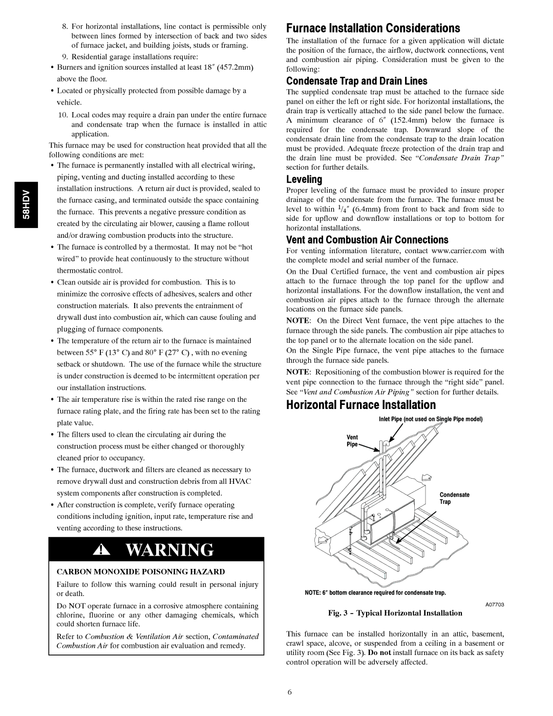
Inlet Pipe (not used on Single Pipe model)
Vent
Pipe
Condensate
Trap
NOTE: 6″ bottom clearance required for condensate trap.
A07703
Fig. 3 - Typical Horizontal Installation
This furnace can be installed horizontally in an attic, basement, crawl space, alcove, or suspended from a ceiling in a basement or utility room (See Fig. 3). Do not install furnace on its back as safety control operation will be adversely affected.
6