INSTALLATION
!WARNING
CARBON MONOXIDE POISONING HAZARD
Failure to follow this warning could result in personal injury or death.
This furnace can NOT be common vented or connected to any type B, BW or L vent or vent connector, nor to any portion of a
problems for the other remaining appliance(s). See Venting and Combustion Air Check in Gas Vent Installation section. This furnace MUST be vented to the outside.
Installation Positions
This furnace can be installed in an upflow, horizontal (either left or right) or downflow airflow position. DO NOT install this furnace on its back. For the upflow position, the return air ductwork can be attached to either the left or right side panel and/or the bottom. For horizontal and downflow positions, the return air ductwork must be attached to the bottom. The return air ductwork must never be attached to the back of the furnace.
Location and Clearances
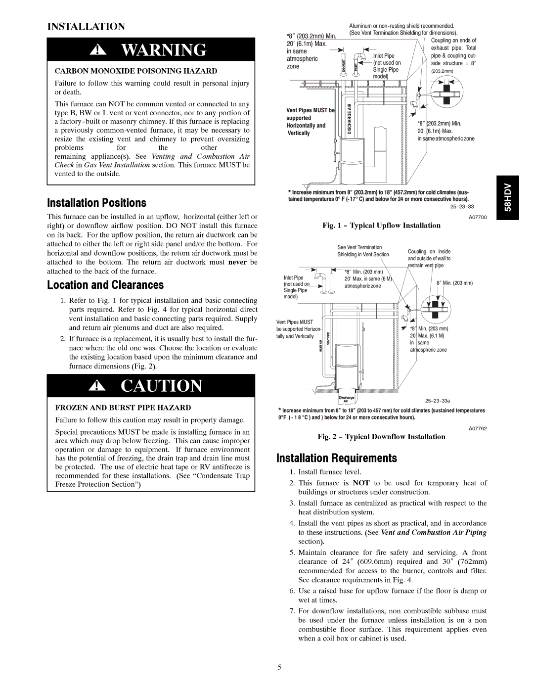
1.Refer to Fig. 1 for typical installation and basic connecting parts required. Refer to Fig. 4 for typical horizontal direct vent installation and basic connecting parts required. Supply and return air plenums and duct are also required.
2.If furnace is a replacement, it is usually best to install the fur- nace where the old one was. Choose the location or evaluate the existing location based upon the minimum clearance and furnace dimensions (Fig. 2).
!CAUTION
FROZEN AND BURST PIPE HAZARD
Failure to follow this caution may result in property damage.
Special precautions MUST be made is installing furnace in an area which may drop below freezing. This can cause improper operation or damage to equipment. If furnace environment has the potential of freezing, the drain trap and drain line must be protected. The use of electric heat tape or RV antifreeze is recommended for these installations. (See “Condensate Trap Freeze Protection Section”)
| Aluminum or | ||
*8″ (203.2mm) Min. | (See Vent Termination Shielding for dimensions). | ||
| Coupling on ends of | ||
20′ (6.1m) Max. |
| ||
| exhaust pipe. Total | ||
in same |
| ||
Inlet Pipe | pipe & coupling out- | ||
atmospheric | |||
(not used on | side structure = 8″ | ||
zone | |||
Single Pipe | (203.2mm) | ||
| |||
| model) |
| |
Vent Pipes MUST be | AIR |
| |
DISCHARGE | 20′ (6.1m) Max. | ||
supported | |||
| *8″ (203.2mm) Min. | ||
Horizontally and |
| ||
|
| ||
Vertically |
| in same atmospheric zone | |
|
|
*Increase minimum from 8″ (203.2mm) to 18″ (457.2mm) for cold climates (sus- tained temperatures 0° F (- 17° C) and below for 24 or more consecutive hours).
A07700
Fig. 1 - Typical Upflow Installation
| See Vent Termination | Coupling on inside |
| Shielding in Vent Section. | |
| and outside of wall to | |
|
| |
| *8″ Min. (203 mm) | restrain vent pipe |
Inlet Pipe |
| |
20′ Max. in same (6 M) | 8″ Min. (203 mm) | |
(not used on | atmospheric zone | |
Single Pipe |
| |
|
| |
model) |
|
|
Vent Pipes MUST |
|
be supported Horizon- | *8″ Min. (203 mm) |
tally and Vertically | 20′ Max. (6.1 M) |
| in same |
| atmospheric zone |
| |
* Increase minimum from 8″ to 18″ (203 to 457 mm) for cold climates (sustained temperatures | |
0°F ( - 1 8 °C ) and ) below for 24 or more consecutive hours). | |
| A07762 |
Fig. 2 - Typical Downflow Installation
Installation Requirements
1.Install furnace level.
2.This furnace is NOT to be used for temporary heat of buildings or structures under construction.
3.Install furnace as centralized as practical with respect to the heat distribution system.
4.Install the vent pipes as short as practical, and in accordance to these instructions. (See Vent and Combustion Air Piping section).
5.Maintain clearance for fire safety and servicing. A front clearance of 24″ (609.6mm) required and 30″ (762mm) recommended for access to the burner, controls and filter. See clearance requirements in Fig. 4.
6.Use a raised base for upflow furnace if the floor is damp or wet at times.
7.For downflow installations, non combustible subbase must be used under the furnace unless installation is on a non combustible floor surface. This requirement applies even when a coil box or cabinet is used.
58HDV
5