2.For
Required Volume fan ² | 15 ft3 | ( |
| I fan | ) |
| 1000 Btu / hr | ||||
|
| ||||
| ACH |
| |||
where:
Iother = all appliances other than
Ifan =
3.For purposes of this calculation, an infiltration rate greater than 0.60 ACH shall not be used in the equations above.
The following requirements apply to the Standard Method and to the Known Air Infiltration Rate Method.
SAdjoining rooms can be considered part of a space, if there are no closeable doors between rooms.
SCombining spaces on the same story. Each opening shall have a minimum free area of at least 1 in.2/1,000 BTUH (2,200 mm2/kW) of the total input rating of all appliances in the space
but not less than 100 in.2 (0.06 m2). One opening shall commence within 12 in. (304.8 mm) of the top, and one opening shall commence within 12 in. (304.8 mm) of the bottom, of the enclosure. The minimum dimension of air openings shall not be less than 3 in. (76.2 mm).
SCombining spaces in different stories. The volumes of spaces on different stories shall be considered as communicating spaces where such spaces are connected by one or more openings in
doors or floors having a total minimum free area of 2 in.2/1,000 BTUH (4,400 mm2/kW) of total input rating of all appliances.
SAn attic or crawl space may be considered a space that freely communicates with the outdoors provided there are adequate ventilation openings directly to outdoors. Openings MUST remain open and NOT have any means of being closed off. Ventilation openings to outdoors MUST be at least 1 square inch
of free area per 4,000 BTUH (550 mm2/kW) of total input rating for all gas appliances in the space.
SIn spaces that use the Indoor Combustion Air Method, infiltration should be adequate to provide air for combustion, ventilation and dilution of flue gases. However, in buildings with unusually tight construction, additional air MUST be provided
using the methods described in section titled Outdoor
Combustion Air Method:
SUnusually tight construction is defined as Construction with:
1.Walls and ceilings exposed to the outdoors have a continu- ous, sealed vapor barrier. Openings are gasketed or sealed and
2.Doors and openable windows are weather stripped and
3.Other openings are caulked or sealed. These include joints around window and door frames, between sole plates and floors, between
Ventilation Air
Some provincial codes and local municipalities require ventilation or
Venting and Combustion Air Check
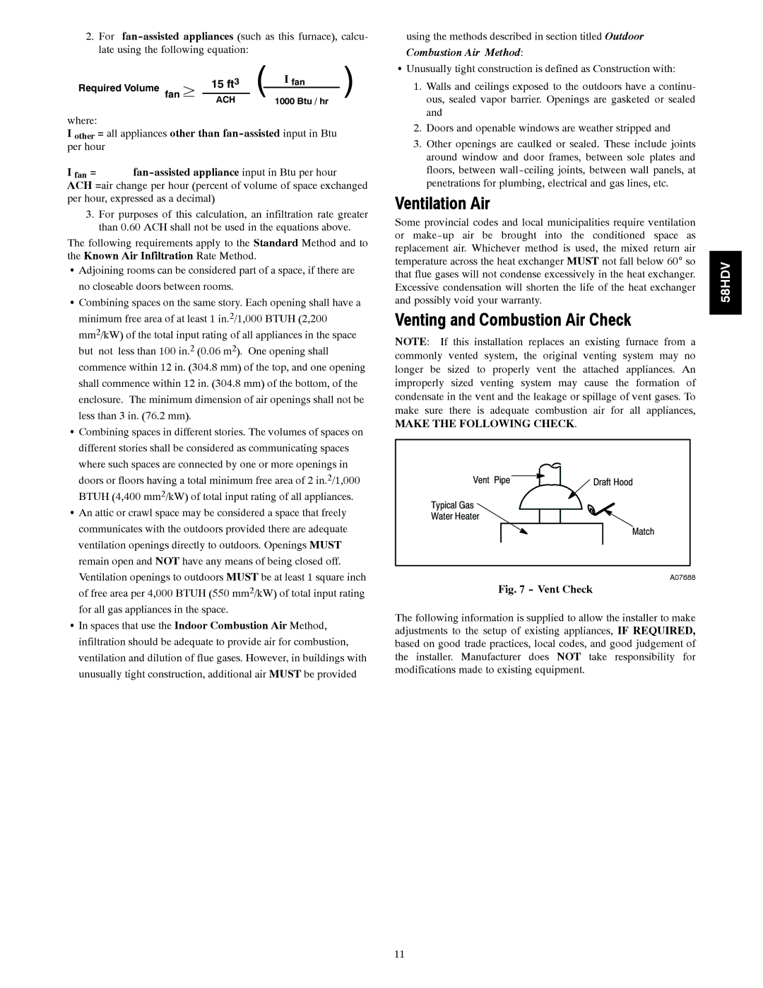
NOTE: If this installation replaces an existing furnace from a commonly vented system, the original venting system may no longer be sized to properly vent the attached appliances. An improperly sized venting system may cause the formation of condensate in the vent and the leakage or spillage of vent gases. To make sure there is adequate combustion air for all appliances,
MAKE THE FOLLOWING CHECK.
Vent | Pipe | Draft Hood |
Typical Gas |
|
|
Water Heater |
|
|
|
| Match |
A07688
Fig. 7 - Vent Check
The following information is supplied to allow the installer to make adjustments to the setup of existing appliances, IF REQUIRED, based on good trade practices, local codes, and good judgement of the installer. Manufacturer does NOT take responsibility for modifications made to existing equipment.
58HDV
11