10.Properly size gas pipe to handle combined appliance load or run gas pipe directly from gas meter or Propane gas regulator.
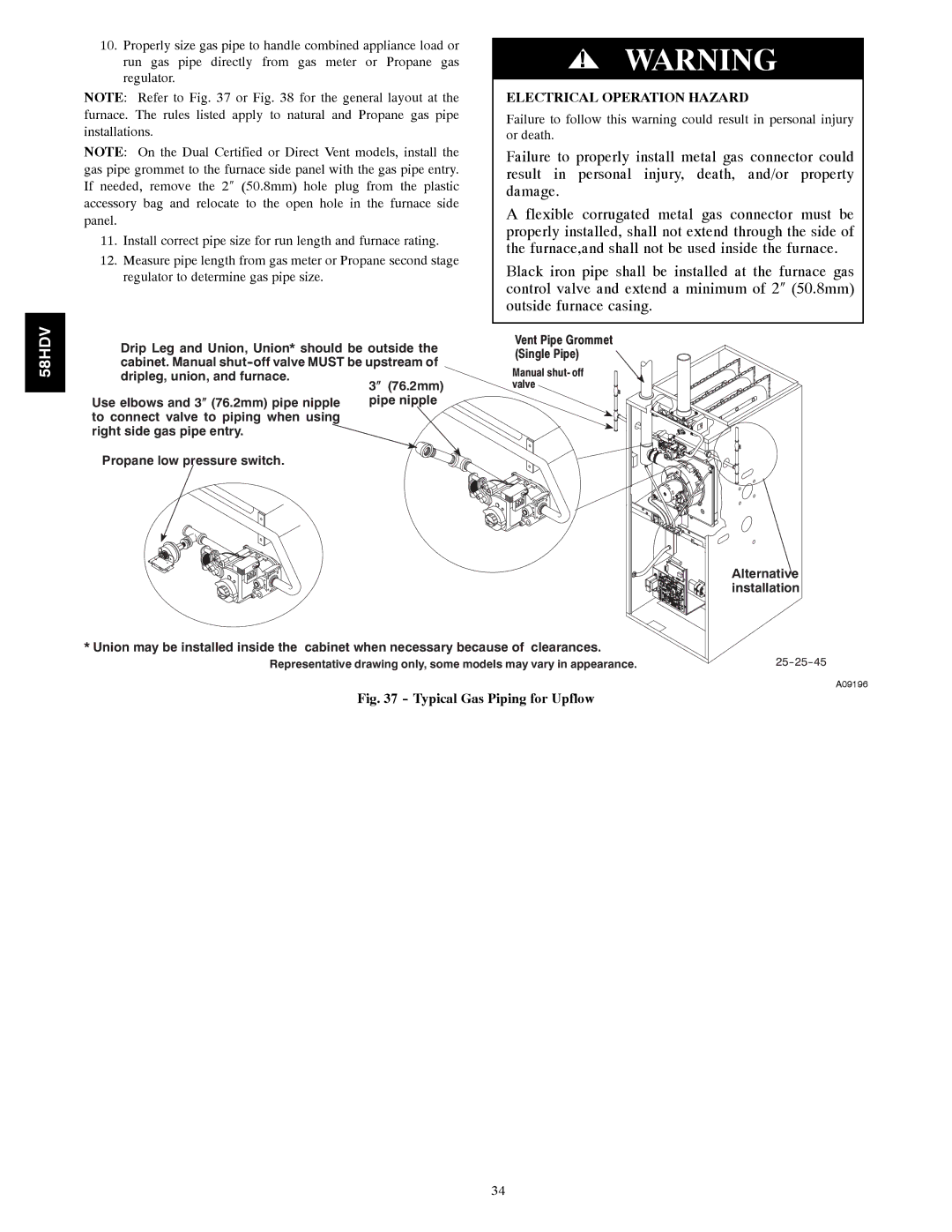
NOTE: Refer to Fig. 37 or Fig. 38 for the general layout at the furnace. The rules listed apply to natural and Propane gas pipe installations.
NOTE: On the Dual Certified or Direct Vent models, install the gas pipe grommet to the furnace side panel with the gas pipe entry. If needed, remove the 2″ (50.8mm) hole plug from the plastic accessory bag and relocate to the open hole in the furnace side panel.
11.Install correct pipe size for run length and furnace rating.
12.Measure pipe length from gas meter or Propane second stage regulator to determine gas pipe size.
!WARNING
ELECTRICAL OPERATION HAZARD
Failure to follow this warning could result in personal injury or death.
Failure to properly install metal gas connector could result in personal injury, death, and/or property damage.
A flexible corrugated metal gas connector must be properly installed, shall not extend through the side of the furnace,and shall not be used inside the furnace.
Black iron pipe shall be installed at the furnace gas control valve and extend a minimum of 2″ (50.8mm) outside furnace casing.
58HDV
Drip Leg and Union, Union* should be outside the cabinet. Manual
Use elbows and 3″ (76.2mm) pipe nipple to connect valve to piping when using right side gas pipe entry.
Propane low pressure switch.
Vent Pipe Grommet (Single Pipe)
Manual shut- off valve
Alternative installation
*Union may be installed inside the cabinet when necessary because of clearances.
Representative drawing only, some models may vary in appearance.
A09196
Fig. 37 - Typical Gas Piping for Upflow
34
