Appendix E Console Cable Pinouts
Overview
Overview
The access point requires a special serial cable that connects the access point serial console port
Console Port Signals and Pinouts
Use the console
Note Both the Ethernet and console ports use
Note After completing your configuration changes, you must remove the serial console cable from the access point.
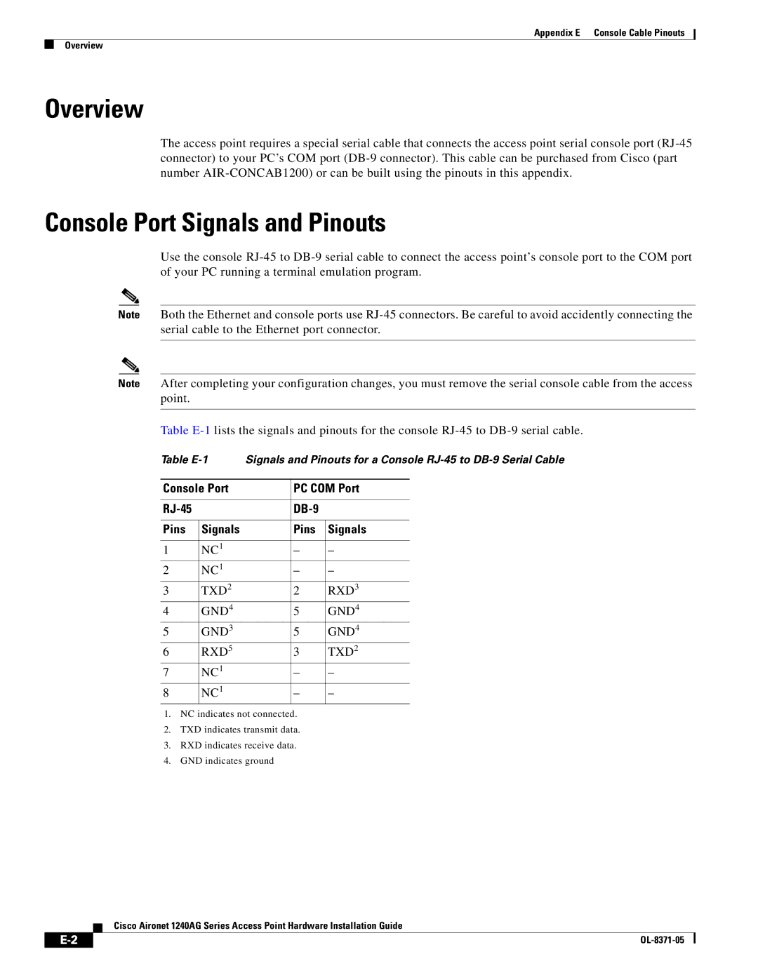
Table
Table | Signals and Pinouts for a Console | ||||
|
|
|
|
| |
Console Port |
| PC COM Port | |||
|
|
|
|
|
|
|
|
|
|
|
|
|
|
|
|
|
|
Pins | Signals |
| Pins | Signals | |
|
|
|
|
|
|
1 | NC1 |
| – | – |
|
2 | NC1 |
| – | – |
|
3 | TXD2 |
| 2 | RXD3 |
|
4 | GND4 |
| 5 | GND4 |
|
5 | GND3 |
| 5 | GND4 |
|
6 | RXD5 |
| 3 | TXD2 |
|
7 | NC1 |
| – | – |
|
8 | NC1 |
| – | – |
|
1.NC indicates not connected.
2.TXD indicates transmit data.
3.RXD indicates receive data.
4.GND indicates ground
Cisco Aironet 1240AG Series Access Point Hardware Installation Guide
|
|
| |
|
|