Chapter 1 Overview
Hardware Features
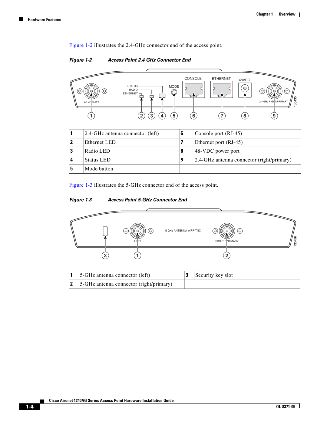
Figure 1-2 illustrates the 2.4-GHz connector end of the access point.
Figure 1-2 Access Point 2.4 GHz Connector End
CONSOLE
STATUSMODE
RADIO
ETHERNET ![]()
2.4 GHz LEFT
1 | 2 | 3 | 4 | 5 | 6 |
ETHERNET 48VDC
2.4 GHz RIGHT/PRIMARY
7 8 9
135435
1 | 6 | Console port | |
|
|
|
|
2 | Ethernet LED | 7 | Ethernet port |
|
|
|
|
3 | Radio LED | 8 | |
|
|
|
|
4 | Status LED | 9 | |
|
|
|
|
5 | Mode button |
|
|
|
|
|
|
Figure 1-3 illustrates the 5-GHz connector end of the access point.
Figure 1-3 Access Point 5-GHz Connector End
5 GHz ANTENNA
LEFT | RIGHT / | PRIMARY |
|
|
|
135436
3 | 1 | 2 |
1
2
3 | Security key slot | |
|
|
|
Cisco Aironet 1240AG Series Access Point Hardware Installation Guide
| ||
|