Chapter 1 Overview
Hardware Features
Single or Dual-Radio Operation
The 1242AG access point supports simultaneous radio operation using a 2.4-GHz 802.11g radio and a 5-GHz 802.11a radio. The 1242G access point supports a single 2.4-GHz 802.11g radio. Each radio uses dual-diversity integrated antennas.
The 5-GHz radio incorporates an Unlicensed National Information Infrastructure (UNII) radio transceiver operating in the UNII 5-GHz frequency bands. The 802.11g radio is called Radio0 and the 802.11a radio is called Radio1.
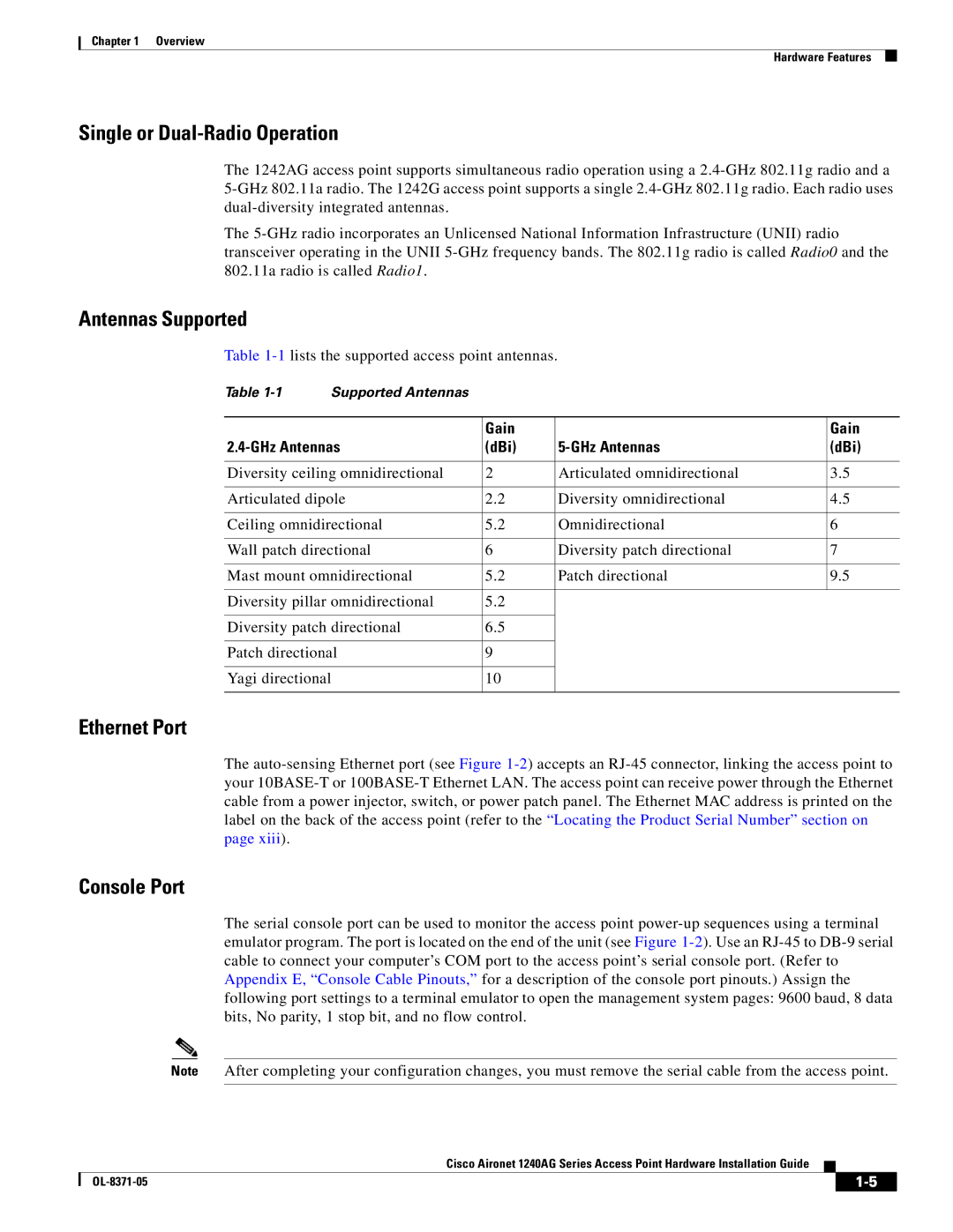
Antennas Supported
Table 1-1lists the supported access point antennas.
Table 1-1 | Supported Antennas | | | |
| | | | |
| | Gain | | Gain |
2.4-GHz Antennas | (dBi) | 5-GHz Antennas | (dBi) |
| | | |
Diversity ceiling omnidirectional | 2 | Articulated omnidirectional | 3.5 |
| | | |
Articulated dipole | 2.2 | Diversity omnidirectional | 4.5 |
| | | |
Ceiling omnidirectional | 5.2 | Omnidirectional | 6 |
| | | |
Wall patch directional | 6 | Diversity patch directional | 7 |
| | | |
Mast mount omnidirectional | 5.2 | Patch directional | 9.5 |
| | | |
Diversity pillar omnidirectional | 5.2 | | |
| | | |
Diversity patch directional | 6.5 | | |
| | | |
Patch directional | 9 | | |
| | | |
Yagi directional | 10 | | |
| | | | |
Ethernet Port
The auto-sensing Ethernet port (see Figure 1-2) accepts an RJ-45 connector, linking the access point to your 10BASE-T or 100BASE-T Ethernet LAN. The access point can receive power through the Ethernet cable from a power injector, switch, or power patch panel. The Ethernet MAC address is printed on the label on the back of the access point (refer to the “Locating the Product Serial Number” section on page xiii).
Console Port
The serial console port can be used to monitor the access point power-up sequences using a terminal emulator program. The port is located on the end of the unit (see Figure 1-2). Use an RJ-45 to DB-9 serial cable to connect your computer’s COM port to the access point’s serial console port. (Refer to Appendix E, “Console Cable Pinouts,” for a description of the console port pinouts.) Assign the following port settings to a terminal emulator to open the management system pages: 9600 baud, 8 data bits, No parity, 1 stop bit, and no flow control.
Note After completing your configuration changes, you must remove the serial cable from the access point.
Cisco Aironet 1240AG Series Access Point Hardware Installation Guide