Americas Headquarters
Text Part Number OL-19084-03
Page
OL-19084-03
Console and Auxiliary Port Considerations
Chassis Airflow Diagram
Configuring the Auxiliary Line
Objectives
Audience
Organization
Conventions
Section Title Description
Convention Indication
Bewaar Deze Instructies
Aviso Instruções Importantes DE Segurança
Warnung Wichtige Sicherheitshinweise
Avvertenza Importanti Istruzioni Sulla Sicurezza
Guarde Estas Instrucciones
GEM Disse Anvisninger
Xiii
Xiv
Related Documentation
Obtaining Documentation and Submitting a Service Request
Searching within Cisco Documents
Safety Warnings
Overview of the Router
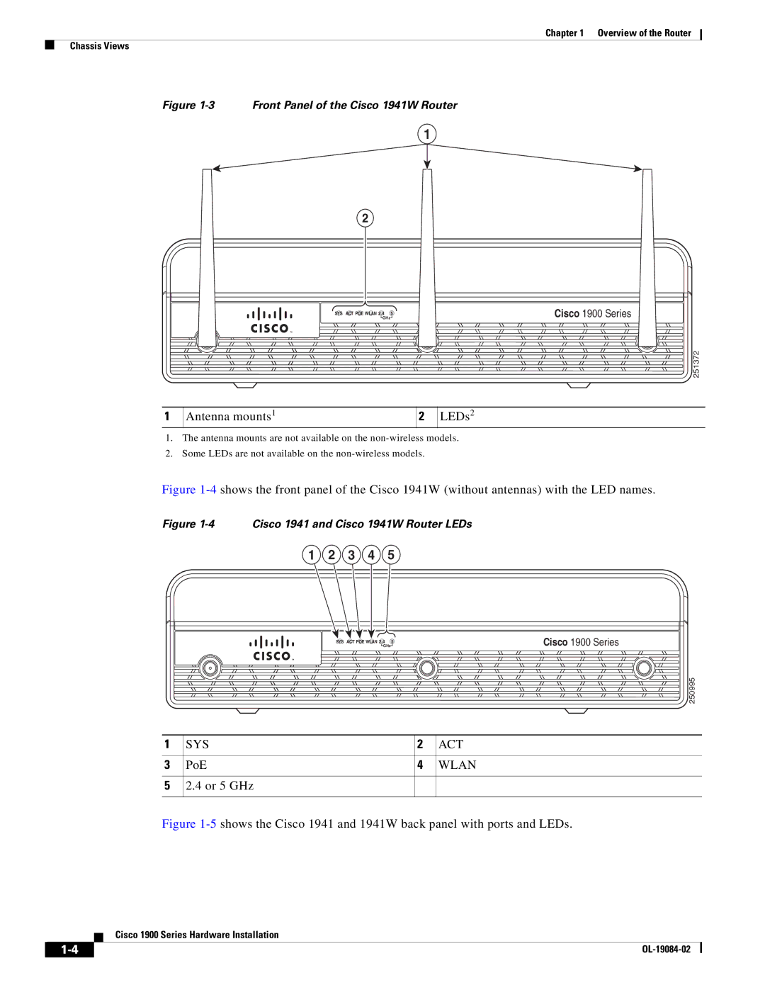
SYS ACT PoE12
Safety Warnings for Finland, Norway and Sweden
Chassis Views
Cisco
Antenna mounts1 LEDs2
SYS ACT
Wlan
4 or 5 GHz
Hardware Features
Overview of the Router Hardware Features
Product Serial Number Location
Clei
Built-In Interfaces
Cisco Product Identification Tool
Product ID PID Compliance label
Clei
Removable, Interchangeable, and Optional Modules
Interface Description
USB
Such as security tokens and flash memory
Memory
External Modules In chassis slots Internal Modules
Series 1905 1921
Dram
SYS
LED Indicators
Color Description Location
ISM/WLAN
Wireless LAN Connectivity
Chassis Ventilation
Real-Time Clock
Chassis Security
Baud Reset Button
Interface Numbering
Slot Number Slot Type Slot Numbering Range
Onboard Ports 10/100/1000 Ethernet
Power
Specifications
Description Specification Physical
Description Specification
Ports
Transportation and Storage Environment
Acoustic
TIA/EIA/IS-968
CNS
Regulatory Compliance
ITU-T G.823, G.824
Safety Recommendations
General Guidelines
Safety with Electricity
General Site Requirements
Preventing Electrostatic Discharge Damage
Site Environment
Power Supply Considerations
Site Configuration
Installation Checklist
Wireless LAN Considerations
Inspecting the Router
Task Verified by
Installation Checklist for Site Router Name
Site Log
Task Verified by Date
Router quick start guide received
Cisco 1900 Series Hardware Installation OL-19084-02
OL-19084-02
Console Port Connections
Console and Auxiliary Port Considerations
About Console and Auxiliary Ports
USB Console OS Compatibility
EIA/TIA-232 Port
USB Serial Console
Preparing to Connect to a Network
Auxiliary Port Connections
Ethernet Connections
Serial Connections
Configuring Serial Connections
Signaling Standards Supported
About Serial Connections
Serial DTE or DCE Devices
Transmission Speeds and Distance Limitations
Asynchronous/Synchronous Serial Module Baud Rates
Distance for
EIA/TIA-232 EIA-530 Distance for USB Rate bps Feet Meters
Isdn BRI Connections
CSU/DSU Connections
Low-Capacitance Cable
For more information on BRI WICs, refer to Cisco.com
Internal services module ISM
About Modules
Internal Modules
Router’s internal components include the following
Plug-In Modules
Setting Up the Chassis
Chassis Airflow Diagram
Wall-Mounting the Chassis
Setting the Chassis on a Desktop
Chassis Grounding
253711
Procedure
Wall-Mounting Features on the Cisco 1941 Router
Rack-Mounting the Chassis
Attaching Rack-Mount Brackets to Cisco 1900 Series Routers
253712
Installing the Chassis Ground Connection
9shows how to attach the brackets to the rack
11 Chassis Ground Connection on the Cisco 1941 Router
Connecting WAN and LAN Cables
Safety Messages
OL-19084-02
Ports and Cabling
Port Type, Color Connected to Cable
Connecting to the Console Port with Microsoft Windows
Connecting to a Console Terminal or Modem
Connection Procedures and Precautions
12 Connecting the Console Cable to the Router
Connecting to the Console Port with Mac OS
Connecting to the Console Port with Linux
Open the Linux Terminal window
Connect the Linux USB port to the router
Before You Begin Procedure
Installing the Cisco Microsoft Windows XP USB Driver
Installing the Cisco Microsoft Windows 2000 USB Driver
Uninstalling the Cisco USB Driver
Installing the Cisco Microsoft Windows Vista USB Driver
Using the Add Remove Programs Utility
Before You Begin
Uninstalling the Cisco Microsoft Windows Vista USB Driver
Using the Setup.exe Program
Connecting to the Auxiliary Port
13 Connecting a Modem to the Router
Connecting Power
Connecting to AC Power
Connecting to DC Power
DC Wiring Requirements for Cisco 1900 Series Routers
Wire Size Wire Terminal Lug Protection
DC Input
Cisco 1900 Series Router Wiring Procedure for DC Input
14 DC Power Wire Connection
15 Installing the Plastic Safety Cover
OL-19084-02
Powering up the Router
Checklist Before Powering Up the Cisco Router
Powering Up the Cisco Router
Related Information
Performing the Initial Configuration on the Router
Using the Cisco Setup Command Facility
5-6 to configure the router
Verifying the Front Panel LED Indications
System displays a summary of the available interfaces
To proceed using the setup command facility, enter yes
Enter a hostname for the router
System creates the following configuration command script
System displays the user prompt
Using Cisco Configuration Professional Express
Using the Cisco CLI-Manual Configuration
Initial CLI Configuration
When the system message appears on the router, enter no
Type enable to enter privileged Exec mode
Press Return to bring up the Router prompt
Configuring the Router Hostname
Command or Action Purpose
Verify that the router prompt displays your new hostname
Example
Configuring the Enable and Enable Secret Passwords
Optional Returns to privileged Exec mode
Configuring the Console Idle Privileged Exec Timeout
Command collection mode
That the privileged Exec command interpreter waits until
Example shows how to specify no timeout. Setting
Exec-timeout value to 0 will cause the router to
Learn which type of Ethernet interface is on your
Configuring Gigabit Ethernet Interfaces
For IP
Configuring the GigabitEthernet Interface
Sample Output for the show ip interface brief Command
Specifying a Default Route or Gateway of Last Resort
Configuring IP Routing and IP Protocols
Routerconfig# ip routing
Gateway of Last Resort
Specifying a Default Route Example
Sample Output for the show ip route Command
Starts the line configuration command collection mode for
Virtual terminal lines vty for remote console access
Make sure that you configure all vty lines on your
Line vty ? command
Configuring the Auxiliary Line
Example
Verifying Network Connectivity
Auxiliary line
Connected host for each configured interface
If you want to test the vty line password, perform this
Diagnoses initial network connectivity
To verify connectivity, ping the next hop router or
Saving Your Router Configuration
Saving Backup Copies of Configuration and System Image
Saves the running configuration to the startup
Configuration
Copying the Startup Configuration to a Tftp Server Example
Copying from Flash Memory to a Tftp Server Example
Verifying the Initial Configuration
Nvram
OL-19084-02
Activating a New Software Package or Feature
Getting Software Licenses for the Router
RMA License Transfer
1shows the steps for software activation
Additional Information
OL-19084-02

![]() GHz
GHz![]()
![]() GHz
GHz![]()
