Chapter 1 Introducing the Cisco Wide Area Virtualization Engine
Hardware Features
Warning To avoid electric shock, do not connect safety
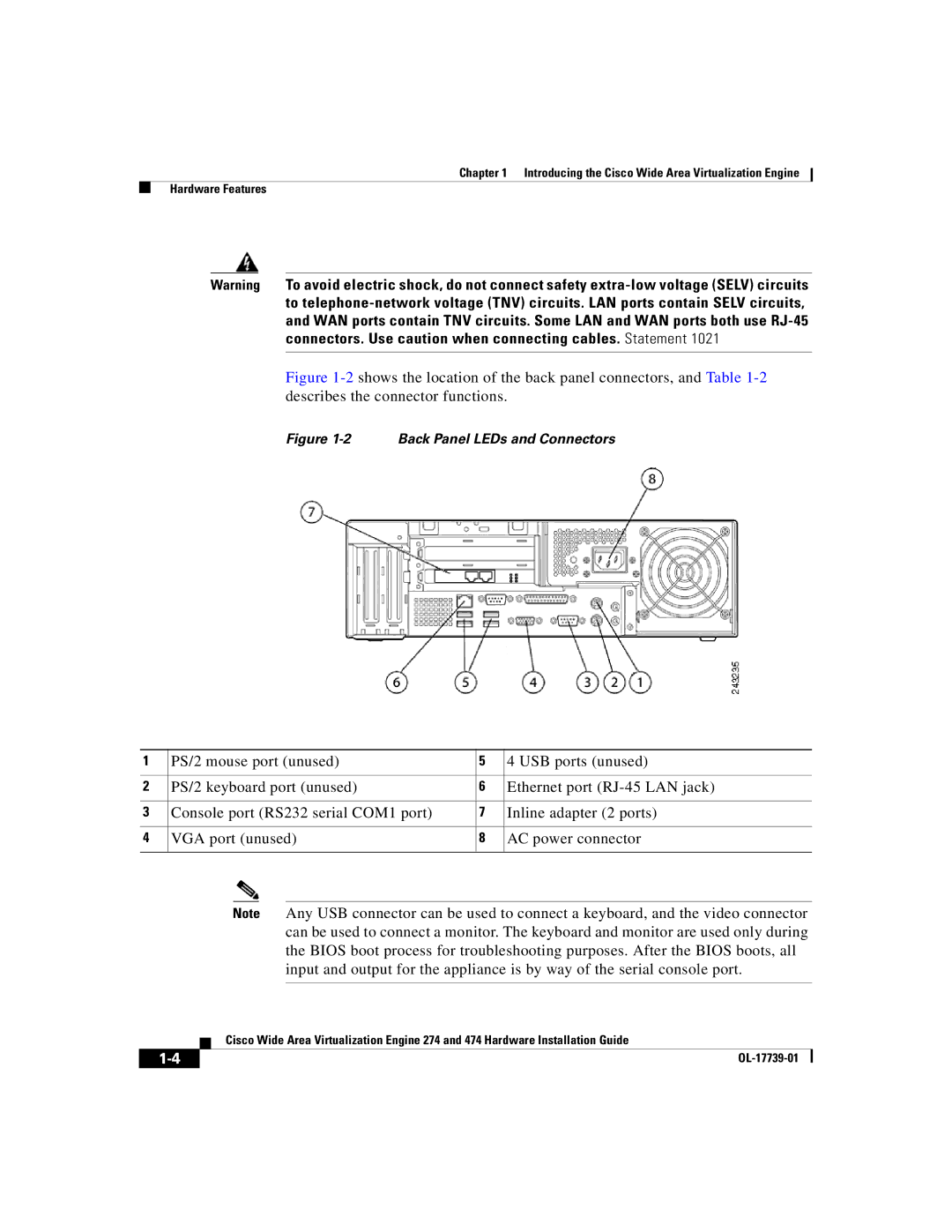
Figure 1-2 shows the location of the back panel connectors, and Table 1-2 describes the connector functions.
Figure 1-2 Back Panel LEDs and Connectors
1 | PS/2 mouse port (unused) | 5 | 4 USB ports (unused) |
|
|
|
|
2 | PS/2 keyboard port (unused) | 6 | Ethernet port |
|
|
|
|
3 | Console port (RS232 serial COM1 port) | 7 | Inline adapter (2 ports) |
|
|
|
|
4 | VGA port (unused) | 8 | AC power connector |
|
|
|
|
Note Any USB connector can be used to connect a keyboard, and the video connector can be used to connect a monitor. The keyboard and monitor are used only during the BIOS boot process for troubleshooting purposes. After the BIOS boots, all input and output for the appliance is by way of the serial console port.
| Cisco Wide Area Virtualization Engine 274 and 474 Hardware Installation Guide |
|