Cisco 7200 VXR Installation and Configuration Guide
Americas Headquarters
Cisco 7200 VXR Installation and Configuration Guide
N T E N T S
MAC Address
Connecting Power
Problem Solving Using a Subsystems Approach
Bit
Contents Cisco 7200 VXR Installation and Configuration Guide
Document Revision History
Document Version Date Change Summary
Document Conventions
Audience
Organization
Chapter Appendix Title Description
Information you must enter is in boldface screen font
Default responses to system prompts are in square brackets
Vertical bars
You press the D key
Waarschuwing Belangrijke Veiligheidsinstructies
Warnung Wichtige Sicherheitsanweisungen
Hinweis Bewahren SIE Diese Sicherheitsanweisungen AUF
Aviso Instruções Importantes DE Segurança
OBS! Spara Dessa Anvisningar
Terms and Acronyms
Related Documentation
Obtaining Documentation and Submitting a Service Request
Xii
Cisco 7200 VXR Product Overview
Physical Description
Cisco 7200 VXR Product Overview Physical Description
Description Specification
Humidity 10 to 90% noncondensing
Software Requirements
Cisco 7204VXR Overview
Cisco 7204VXR Router-Front View
PWR OK LED
Cisco 7204VXR Router-Rear View
Cisco 7206VXR Overview
Cisco 7206VXR Router-Front View
Cisco 7206VXR Router-Rear View
Field-Replaceable Units
Network Processing Engine or Network Services Engine
Cisco 7200 VXR Product Overview Field-Replaceable Units
Cisco 7200 VXR Product Overview Field-Replaceable Units
Cisco 7200 VXR Product Overview Field-Replaceable Units
Sdram GB DDR Sdram
Nonvolatile Eprom for U17 System configuration file
Memory Type Size Quantity Description
Nvram
GB Dimm
Total Sdram Sdram Bank Quantity
Dimm
Sdram
On the NPE-G1
Memory Type Size Quantity Description Board
Total Sdram Sdram Bank Quantity Product Number
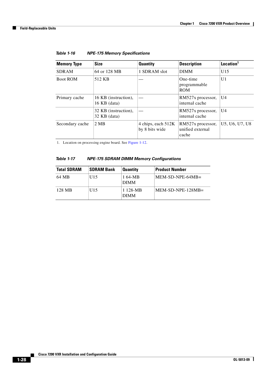
Memory Type Size Quantity Description Location
MEM-SD-NSE-256MB=
MEM-SD-NPE-128MB=
Sodimm J1
MB Sodimm
Sodimm
Total Sdram Bank Quantity Product Number
MEM-NPE-400-512MB=
Memory Type Size
Description Location1
MEM-SD-NPE-32MB=
Total Sdram Sdram Bank 1 Quantity Product Number
MEM-SD-NPE-64MB=
Sdram Dimm U15
Sdram Dimm
Boot ROM 512 KB One-time Programmable
64, 128, 256 MB Sdram slot 64-MB, 128- MB U15 Or 256-MB
ROM
Dram
Sram
MEM-NPE-32MB=
Total Product Number
Dram Bank Quantity
MEM-NPE-64MB=
NPE-175
64 MB U15 64-MB
64 or 128 MB Sdram slot
128 MB U15 128-MB
NPE-150 Memory Specifications
64 MB U18 and U25 MB SIMMs U4 and U12
Total Dram Dram Bank Quantity Product Number
32 MB U18 and U25 MB SIMMs U4 and U12
128 MB U18 and U25 MB SIMMs U4 and U12 32-MB
Total Dram Dram Bank Quantity
Determining Memory Configuration
Quantity Product Number
Input/Output Controller
Product Number Description
910
84525
Temperature sensor Console port Captive installation screw
Nvram U41
Slot CIA EJE
19 C7200-I/O-Without Fast Ethernet Port Version
LED
20 C7200-I/O-Without Fast Ethernet Port Version
Temperature sensor Console port
21 C7200-I/O-FE-MII-With Single MII Fast Ethernet Receptacle
23lists the I/O controller memory components
LED Descriptions
Type Size Quantity Memory Description Model Location
Color Function
Color Status in the Power Up State
NPE-G2 LEDs
LED Label
Color
NPE-G1 LEDs
There Is Traffic
Input/Output Controller C7200-I/O LEDs
Input/Output Controller C7200-I/O-GE+E LEDs
Input/Output Controller C7200-I/O-2FE/E LEDs
Link
Input/Output Controller C7200-I/O-FE LEDs
RJ45 EN
MII EN
RJ45 Link
FE Enable
Port Adapters and Service Adapters
Input/Output Controller C7200-I/O-FE-MII LEDs
Port Adapter Jacket Card
Captive installation screw Handle
Enable LED
Port adapter slot
Power Supplies
Power cable- retention clip
OK LED
Chassis
CompactFlash Disks, Flash Disks, and PC Cards
30 Cisco 7200 VXR Chassis-7206VXR Shown
Memory Size
Functional Overview
Rack-Mount and Cable-Management Kit
Product Number1
Chassis Slot and Logical Interface Numbering
Cisco
32 Port Adapter Slot Numbering-Cisco 7206VXR
Router# show interfaces
MAC Address
Online Insertion and Removal
Cisco 7200 VXR Product Overview Functional Overview
Environmental Monitoring and Reporting Functions
Environmental Monitoring
NPE-G1 Low Warning High Warning Shutdown
NPE-G2 Low Warning High Warning Shutdown
Parameter High Warning High Critical Shutdown
Parameter Low Critical High Critical
Reporting Functions
NPE300boot# show environment last
NPE300boot# show environment all
Fan Failures
Preparing for Installation
Tools and Parts Required
Electrical Equipment Guidelines
Preventing Electrostatic Discharge Damage
Site Requirement Guidelines
1shows the airflow through the router
Internal Airflow-Top View
Rack-Mounting Guidelines
Cisco 7200 VXR Router Footprint and Outer Dimensions
Temperature and Humidity Requirements
Specification Minimum Maximum
Plant Wiring Guidelines
Power Connection Guidelines
Interference Considerations
Initial Configuration Information
Distance Limitations and Interface Specifications
Cisco 7200 VXR Router Installation Checklist
Task Verified By Date
Checking the Shipping Container Contents
Site Log
Component Description Received
Site Log Sample
Installing a Cisco 7200 VXR Router
Rack-Mounting a Cisco 7200 VXR Router
Typical Four-Post Equipment Rack Posts and Mounting Strips
Rack-mount bracket
Eries
84520
Rack-mount bracket Cable-management bracket
Cisco Series
84547
Installing the Brackets on the Front of the Chassis
Cisco Series VXR
84545
66749
Installing the Brackets on the Rear of the Chassis
247639
66750
General Tabletop or Workbench Installation
Installing the Chassis in the Rack
Installing the Cable-Management Brackets
Service loop
Securing the Port Adapter Cables
Attaching a Chassis Ground Connection
84530
Connecting I/O Controller, NPE-G1, or NPE-G2 Cables
Connecting Port Adapter Cables
Connecting to Gigabit Ethernet Slots and Ports
Gigabit Ethernet SFP Module Connections
15 Laser Class 1 Warning Label
Specification Description
SFP-GE-F=
100BASE-FX
MMF
1000BASE-LX/LH
Mode-Conditioning Patch Cord Description
4provides NPE-G2 Cwdm SFP module configuration information
Cwdm Product Number Color
17 Mode-Conditioning Patch Cord Assembly for an SFP Module
Gigabit Ethernet Gbic Connections
Gigabit Ethernet Gbic Product Number
GBIC-LX/LH= 1000BASELX/LH
Gbic Cabling and Connection Equipment
GBIC-SX=
GBIC-ZX-SM=
Wavelength Core Size
Transmit Power Receive Power
Minimum Maximum Power Budget
Fiber Type Micron MHz/km Cable Distance
19 Gbic Mode-Conditioning Patch Cord Assembly
Gigabit Ethernet RJ-45 Connections on the NPE-G1 and NPE-G2
Pin 10/100 Signal Gigabit Ethernet Signal
Tx Data+ Tx A+ Tx a Rx Data+ Rx B+ Tx C+ Rx D+
Pin Description
RJ-45 connector and port
Ethernet and Fast Ethernet RJ-45 Connections
TxD+1 RxD+2
Router Hub
25 Crossover or Straight-Through Cable Identification
Fast Ethernet MII Connections
26 Fast Ethernet Port Connection
Pin Jackscrew
Connecting to the Console and Auxiliary Ports
Pin Out Description
DB-25 Port Cabling and Pinouts
Model Console Port Auxiliary Port
DSR
Pin Signal Direction Description
GND
DCD
CTS
RJ-45 Port Cabling and Pinouts
RTS
DTR
Console and Auxiliary Port RJ-45 Connector
Adapter DTE M/F Pins DCE M/F Pins Mmod Pins
Pin Pin 1 and pin 8 should be the same color
Pin1 Signal Direction Description
DSR/DCD
Connecting Power
Rlsd
Connecting AC-Input Power
Connecting DC-Input Power
32 Stripping the DC-Input Leads
33 Connecting DC-Input Power
Basic Configuration
Checking Conditions Prior to System Startup
Starting the System and Observing Initial Conditions
Configuring a Cisco 7200 VXR Router
Performing a Basic Configuration Using AutoInstall
Performing a Basic Configuration Using the Setup Facility
Configuring Global Parameters
Restricted Rights Legend
Enter enable secret, enable, and virtual terminal passwords
Enter enable secret barney
Page
Following speed/duplex settings are supported
Configuring the Native Gigabit Ethernet Interfaces
Configuring the Interface Transmission and Speed Modes
Example
Sample Configuration
Be needed, depending on the nature of the connected network
Configuring ATM Interfaces
Configuring Port Adapter Interfaces
Resetting the Interface on the NPE-G1 or NPE-G2
Debugging
Configuring Fast Ethernet Interfaces
Configuring Synchronous Serial Interfaces
Snmp-server community public Ip routing
Prompt changes to the privileged Exec prompt
Saving the Running Configuration to Nvram
Performing Other Configuration Tasks
Checking the Running Configuration Settings
Using show Commands to Check the Installation
Model Interface Numbers Syntax
Replacing or Recovering a Lost Password
Overview of the Password Recovery Procedure
Details of the Password Recovery Procedure
Press Return. The user Exec prompt is displayed as follows
Change all three passwords using the following commands
Viewing Your System Configuration
Router# show diag
FF FF
Performing Complex Configurations
Troubleshooting the Installation
Troubleshooting Overview
Problem Solving Using a Subsystems Approach
Action Yes
Power LEDs
Identifying Startup Problems
Fans Operating
Controller LEDs
NPE-G1 or NPE-G2 LEDs
Port Adapter Jacket Card LEDs
Troubleshooting the Power Subsystem
System Bootup Banner
Port Adapter LEDs
Troubleshooting the Processor Subsystem
Troubleshooting the I/O Controller
Troubleshooting the NPE-G1 or NPE-G2
Troubleshooting the Port Adapter Jacket Card
Troubleshooting the Port Adapters or Service Adapters
Troubleshooting the Cooling Subsystem
Fiber-Optic Cleaning Information
Following information is found in this appendix
Configuration Bit Meanings
Bit No Hex Meaning
Boots the boot helper image as a system image
Boot Field Meaning
Bits
Bit
Action/File Name Bit
Bit IP Address net host
Bit 10 and Bit
Bit 11 and Bit
Baud Bit
Appendix a Configuration Register Information
Setting the Configuration Register While Running Cisco IOS
Ignore system config info? y/n
OL-5013-09
D E
MAC
Igrp
IN-2
EMP
Simm cautions and configurations
Eeprom
ESD
NPE NSE
Configuring Jacket card, port adapter LEDs
Handles
IPX
NPE-G1 NPE-G2
Cwdm SFP module configurations
NPE
NSE-1
PXF
IN-6
RIP
Snmp
IN-8