Cisco Systems GRP-B manual Connecting to the Console Port, Console and Auxiliary Port Connections

Models: GRP GRP-B

1 56
Download 56 pages 1.86 Kb
Page 18
Image 18
Connecting to the Console Port

Replacing a GRP

Connecting to the Console Port

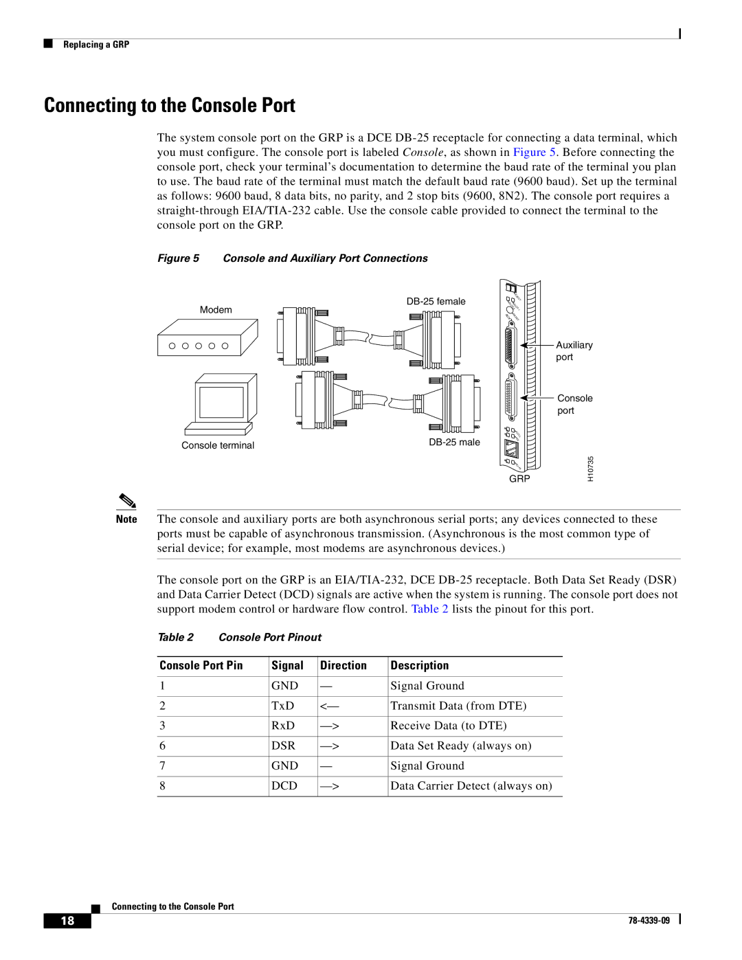
The system console port on the GRP is a DCE DB-25 receptacle for connecting a data terminal, which you must configure. The console port is labeled Console, as shown in Figure 5. Before connecting the console port, check your terminal’s documentation to determine the baud rate of the terminal you plan to use. The baud rate of the terminal must match the default baud rate (9600 baud). Set up the terminal as follows: 9600 baud, 8 data bits, no parity, and 2 stop bits (9600, 8N2). The console port requires a straight-through EIA/TIA-232 cable. Use the console cable provided to connect the terminal to the console port on the GRP.

Figure 5 Console and Auxiliary Port Connections

DB-25 female

Modem


E


JE


C


T

S


L S

O L


T O


-

T


0

-


1

AUX

R

E


E


S


T

Figure 5 Console and Auxiliary Port Connections Auxiliary port

Console terminal

DB-25 male


Console Port Pinout Console port

L


IN


K

C

T

O

XLL

R

X

M


H10735

II


R


J


-


4


5


GRP

Note The console and auxiliary ports are both asynchronous serial ports; any devices connected to these ports must be capable of asynchronous transmission. (Asynchronous is the most common type of serial device; for example, most modems are asynchronous devices.)

The console port on the GRP is an EIA/TIA-232, DCE DB-25 receptacle. Both Data Set Ready (DSR) and Data Carrier Detect (DCD) signals are active when the system is running. The console port does not support modem control or hardware flow control. Table 2 lists the pinout for this port.

Table 2

Console Port Pinout


Console Port Pin

Signal

Direction

Description


1


GND

Signal Ground


2


TxD

<—

Transmit Data (from DTE)


3


RxD

—>

Receive Data (to DTE)


6


DSR

—>

Data Set Ready (always on)


7


GND

Signal Ground


8


DCD

—>

Data Carrier Detect (always on)


Connecting to the Console Port

18

78-4339-09


Page 18
Image 18
Cisco Systems GRP-B manual Connecting to the Console Port, Console and Auxiliary Port Connections, Console Port Pinout