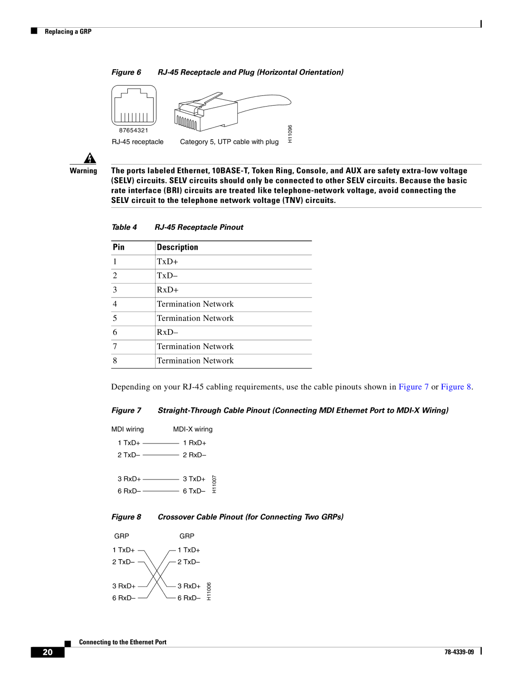
Document Contents
Preparing for Installation, page Replacing a GRP, page
GRP Boot Process Overview, page
Configuring the Ethernet Interface, page
Important Information
Router Information
Supported Platforms
GRP Redundancy
Cisco IOS Configuration Fundamentals Configuration Guide
Cisco IOS Configuration Fundamentals Command Reference
Product Overview
Cisco IOS Software Requirements
GRP Components
Cisco IOS Software
Figure 2 GRP Horizontal Orientation
slot 1 top
DRAM SRAM NVRAM Flash Memory
Memory Components
DRAM
Flash Memory
SRAM
NVRAM
Soft Reset Switch
System Status LEDs
Status LEDs
Display LEDs
Ethernet Port
Flash Card Slots
Asynchronous Serial Ports
Preparing for Installation
Safety Guidelines
Translated Safety Warnings and Agency Approvals
Safety Guidelines Translated Safety Warnings and Agency Approvals
Electromagnetic Compatibility Regulatory Statements
FCC Class A Compliance
CISPR
Canada
VCCI Class A Notice for Japan
Class A Notice for Hungary
Class A Notice for Taiwan and Other Traditional Chinese Markets
Class A Notice for Korea
Preventing Electrostatic Discharge
Working with Electrical Equipment
Removing a GRP
Replacing a GRP
Required Tools and Parts
Figure 4 shows the ejector levers
Replacing a GRP
a Loosen captive screws
Pivot ejector
levers away
Installing a GRP
Console Port Pinout
Connecting to the Console Port
Figure 5 Console and Auxiliary Port Connections
Connecting to the Auxiliary Port
Connecting to the Ethernet Port
Ethernet Interface Cable Connection Procedure
Ethernet Interface Receptacles, Cables, and Pinouts
Crossover Cable Pinout for Connecting Two GRPs
MDI wiring 1 TxD+ 2 TxD 3 RxD+ 6 RxD
MDI-X wiring 1 RxD+ 2 RxD
Figure 6 RJ-45 Receptacle and Plug Horizontal Orientation
Table 5 MII Receptacle Pinout
MII Connections
Figure 9 MII Receptacle Horizontal Orientation
100BASE-TX
Ethernet Interface Cable Connection Procedure
RJ-45
MII cable
Figure 10 Connecting MII or RJ-45 Cables to GRP Vertical Orientation
To repeater or DTE RJ-45 cable To transceiver, repeater, or DTE
GRP Boot Process Overview
Starting the System and Observing Initial Conditions
PROCESSOR
nnnn
0117
You must meet the following criteria to successfully boot the GRP
Verifying Interface Status
Configuring the Ethernet Interface
MII RJ
Using the setup Command Facility to Configure the Ethernet Interface
Using Configuration Mode to Configure the Ethernet Interface
Using Configuration Mode to Configure the Ethernet Interface, page
Configuring the Software Configuration Register
Recovering Lost Password Upgrading GRP Memory
Flash Disks and Flash Memory Cards in the GRP
Boot Field Settings and the boot Command
Changing Configuration Register Settings
Configuration Register Bit Meanings
Default Boot Filenames
Table 11 Default Boot Filenames continued
Table 13 System Console Terminal Transmission Rate Settings
Installing and Removing Flash Memory Card or Flash Disk in GRP
ATA Flash Disk Boot Image Support Requirements
Specifying Cisco IOS Image Used to Boot the System
Figure 14 Installing and Removing Flash Memory Card or Flash Disk
ATA Flash Disk Boot Image Support Requirements
Notes About ATA Flash Disks
Formatting a Flash Memory Card or Flash Disk
Routerconfig# config-reg
To format a new Flash memory card or Flash disk, follow these steps
Specifying Cisco IOS Image Used to Boot the System
Software Commands Associated with Flash Memory
Routerconfig# no boot system
6 679 May 10 1997 054356 todays-config 7 1 May 10 1997 095453 fun1
Enabling Booting from Flash Memory
Copying Files to Flash Memory
Routerconfig#config-reg
Routerconfig#boot system disk0gsr-p-mz.120-17.S
Router#copy running-config startup-config
Router# copy tftpnew.image slot0new.image
Router# copy slot1image.new slot0image.new
Router# show boot display text omitted
Router# copy startup-config slot0myfile2
Router# dir slot0
Step 1 Use the copy running-config slot0filename command as follows
Recovering Lost Password
Recovering from Locked Blocks in Flash Memory Cards or Flash Disks
Step 7 Initialize the router by entering the i command as follows
Upgrading GRP Memory
Total Route Memory
Ordered1
Cisco Product Number
DIMM Modules
Removing DIMMs
Installing New DIMMs
Figure 17 Handling a DIMM
Cisco.com
Checking the DIMM Installation
Obtaining Documentation
Documentation Feedback
Obtaining Technical Assistance
Ordering Documentation
Cisco TAC Website
Obtaining Additional Publications and Information
Opening a TAC Case
TAC Case Priority Definitions
http//tools.cisco.com/RPF/register/register.do
http//cisco.com/univercd/cc/td/doc/pcat