Starting the System and Observing Initial Conditions
For
Step 2 Listen for the system blower modules or fan trays in the router; you should immediately hear them operating. In a noisy environment, place your hand in front of the exhaust vents to verify that the blower modules are operating.
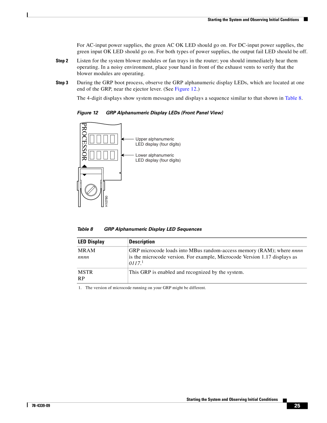
Step 3 During the GRP boot process, observe the GRP alphanumeric display LEDs, which are located at one end of the GRP, near the ejector lever. (See Figure 12.)
The
Figure 12 GRP Alphanumeric Display LEDs (Front Panel View)
PROCESSOR
![]() Upper alphanumeric
Upper alphanumeric
LED display (four digits)
![]() Lower alphanumeric
Lower alphanumeric
LED display (four digits)
H10780 |
Table 8 | GRP Alphanumeric Display LED Sequences | |
|
| |
LED Display | Description | |
|
|
|
MRAM |
| GRP microcode loads into MBus |
nnnn |
| is the microcode version. For example, Microcode Version 1.17 displays as |
|
| 0117.1 |
MSTR |
| This GRP is enabled and recognized by the system. |
RP |
|
|
|
|
|
1. The version of microcode running on your GRP might be different.
Starting the System and Observing Initial Conditions
| 25 |
| |
|
|