Replacing a GRP
MII Connections
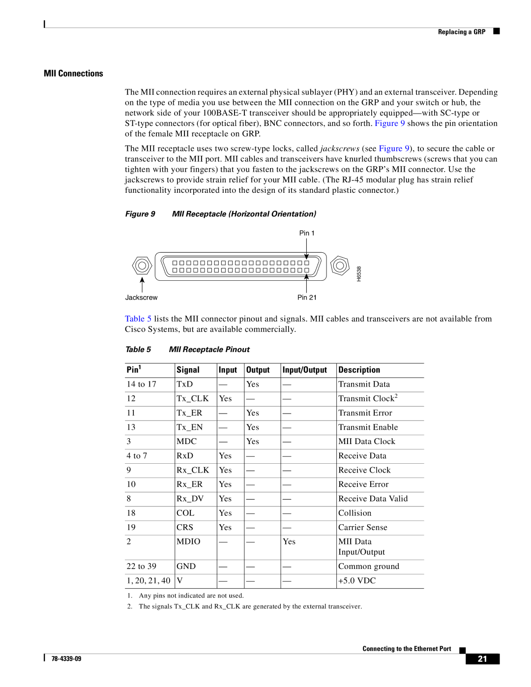
The MII connection requires an external physical sublayer (PHY) and an external transceiver. Depending on the type of media you use between the MII connection on the GRP and your switch or hub, the network side of your
The MII receptacle uses two
Figure 9 MII Receptacle (Horizontal Orientation)
Pin 1
H6538
Jackscrew | Pin 21 |
Table 5 lists the MII connector pinout and signals. MII cables and transceivers are not available from Cisco Systems, but are available commercially.
Table 5 MII Receptacle Pinout
Pin1 | Signal | Input | Output | Input/Output | Description |
14 to 17 | TxD | — | Yes | — | Transmit Data |
|
|
|
|
|
|
12 | Tx_CLK | Yes | — | — | Transmit Clock2 |
11 | Tx_ER | — | Yes | — | Transmit Error |
|
|
|
|
|
|
13 | Tx_EN | — | Yes | — | Transmit Enable |
|
|
|
|
|
|
3 | MDC | — | Yes | — | MII Data Clock |
|
|
|
|
|
|
4 to 7 | RxD | Yes | — | — | Receive Data |
|
|
|
|
|
|
9 | Rx_CLK | Yes | — | — | Receive Clock |
|
|
|
|
|
|
10 | Rx_ER | Yes | — | — | Receive Error |
|
|
|
|
|
|
8 | Rx_DV | Yes | — | — | Receive Data Valid |
|
|
|
|
|
|
18 | COL | Yes | — | — | Collision |
|
|
|
|
|
|
19 | CRS | Yes | — | — | Carrier Sense |
|
|
|
|
|
|
2 | MDIO | — | — | Yes | MII Data |
|
|
|
|
| Input/Output |
|
|
|
|
|
|
22 to 39 | GND | — | — | — | Common ground |
|
|
|
|
|
|
1, 20, 21, 40 | V | — | — | — | +5.0 VDC |
|
|
|
|
|
|
1.Any pins not indicated are not used.
2.The signals Tx_CLK and Rx_CLK are generated by the external transceiver.
Connecting to the Ethernet Port
| 21 |
| |
|
|
