Configuring the Ethernet Interface
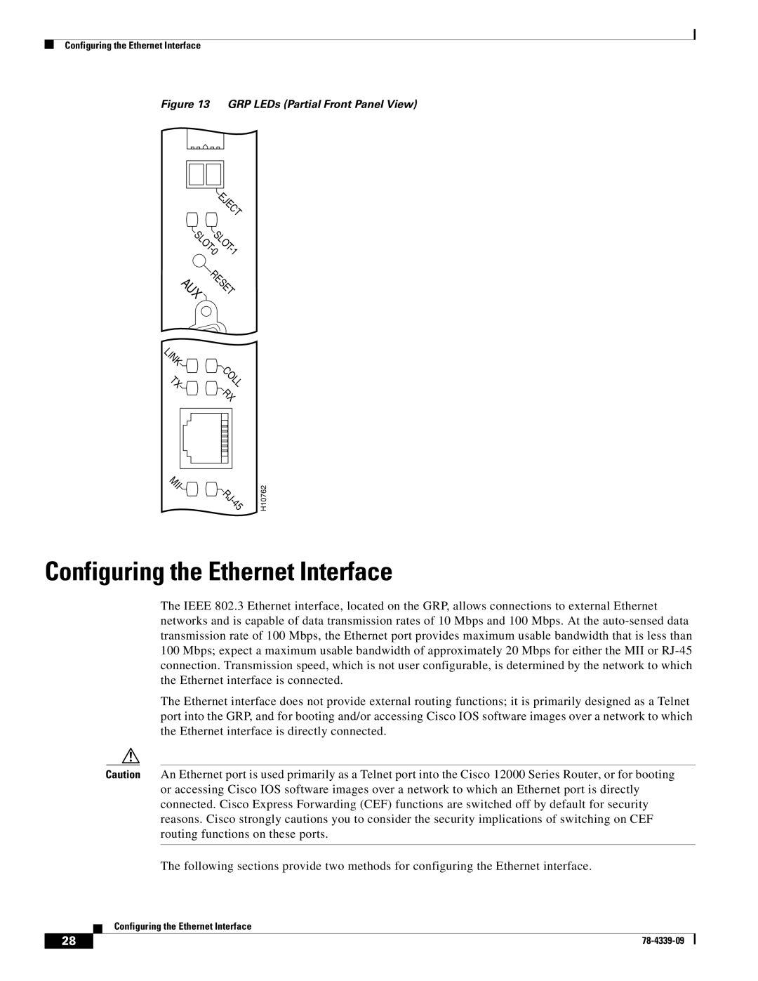
Figure 13 GRP LEDs (Partial Front Panel View)
EJECT | |
SLOTSLOT | |
- | - |
0 | 1 |
AUX RESET | |
LINK |
|
TX | COLL |
| RX |
MII
RJ - 45
H10762
Configuring the Ethernet Interface
The IEEE 802.3 Ethernet interface, located on the GRP, allows connections to external Ethernet networks and is capable of data transmission rates of 10 Mbps and 100 Mbps. At the
The Ethernet interface does not provide external routing functions; it is primarily designed as a Telnet port into the GRP, and for booting and/or accessing Cisco IOS software images over a network to which the Ethernet interface is directly connected.
Caution An Ethernet port is used primarily as a Telnet port into the Cisco 12000 Series Router, or for booting or accessing Cisco IOS software images over a network to which an Ethernet port is directly connected. Cisco Express Forwarding (CEF) functions are switched off by default for security reasons. Cisco strongly cautions you to consider the security implications of switching on CEF routing functions on these ports.
The following sections provide two methods for configuring the Ethernet interface.
Configuring the Ethernet Interface
28 |
| |
|