Replacing a GRP
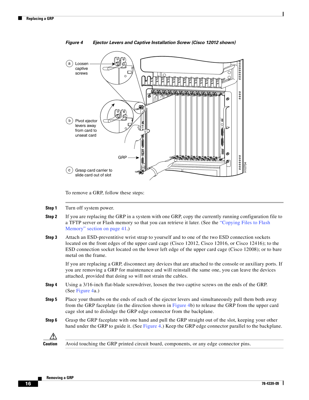
Figure 4 Ejector Levers and Captive Installation Screw (Cisco 12012 shown)
a Loosen captive screws
b | Pivot ejector |
|
|
| CRITIC |
|
|
|
|
| M AL |
| |||
|
|
| MAJOR |
| |||
|
|
| INOR |
| |||
| levers away |
|
| /LT |
| ||
|
|
| EJ |
|
|
| |
|
|
|
| ECT |
|
|
|
|
| SLO SLO |
| ACO |
| ||
| from card to | A | RES |
|
|
| |
| UX |
| ET |
|
|
| |
|
|
|
|
|
| ALARM 1 | |
| unseat card |
|
|
|
|
| |
| C |
|
|
|
|
| |
|
| ONS |
|
|
|
|
|
|
| OLE |
|
|
|
|
|
|
|
|
|
|
|
| ALARM 2 |
|
|
|
|
| EN |
|
|
|
| LINK |
|
| ABLEDFAIL |
| |
|
|
|
| C |
| 0 |
|
|
| TX |
| OLL |
| 1 | CSC |
|
|
|
| RX |
| ||
|
|
|
|
|
| 0 |
|
|
|
|
|
|
| 1 |
|
|
|
|
|
| ALARM | 2 | SFC |
|
| M |
|
|
| ||
|
| II |
| R |
|
|
|
|
| GRP |
|
|
|
|
|
c Grasp card carrier to | GIGABITROUTE PROCESSOR |
|
|
|
| H10704 | |
| slide card out of slot |
|
|
|
|
|
|
To remove a GRP, follow these steps:
Step 1 Turn off system power.
Step 2 If you are replacing the GRP in a system with one GRP, copy the currently running configuration file to a TFTP server or Flash memory so that you can retrieve it later. (See the “Copying Files to Flash Memory” section on page 41.)
Step 3 Attach an
If you are replacing a GRP, disconnect any devices that are attached to the console or auxiliary ports. If you are removing a GRP for maintenance and will reinstall the same one, you can leave the devices attached, provided that doing so will not strain the cables.
Step 4 Using a
Step 5 Place your thumbs on the ends of each of the ejector levers and simultaneously pull them both away from the GRP faceplate (in the direction shown in Figure 4b) to release the GRP from the upper card cage slot and to dislodge the GRP edge connector from the backplane.
Step 6 Grasp the GRP faceplate with one hand and pull the GRP straight out of the slot, keeping your other hand under the GRP to guide it. (See Figure 4.) Keep the GRP edge connector parallel to the backplane.
Caution Avoid touching the GRP printed circuit board, components, or any edge connector pins.
Removing a GRP
16 |
| |
|
