Cisco IE 3000 Switch Getting Started Guide
Warning This product relies on the building’s installation for
Warning Only trained and qualified personnel should be allowed to install, replace, or service this equipment. Statement 1030
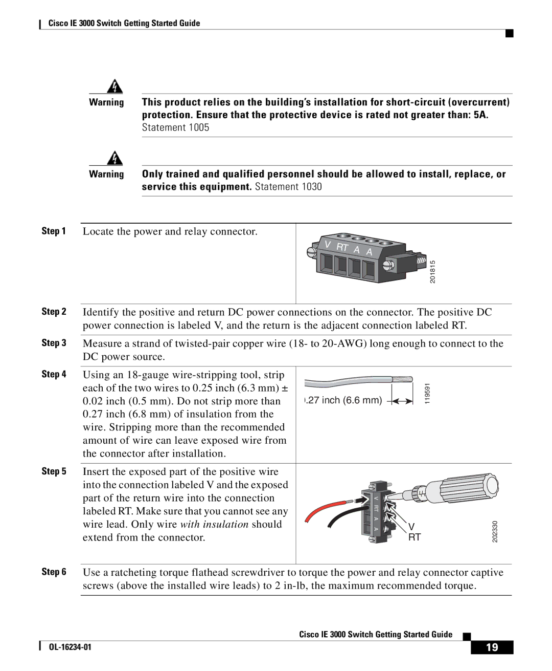
Step 1 Locate the power and relay connector. ![]()
![]()
![]()
![]() 201815
201815
Step 2 Identify the positive and return DC power connections on the connector. The positive DC power connection is labeled V, and the return is the adjacent connection labeled RT.
Step 3 Measure a strand of
Step 4 Using an
0.02inch (0.5 mm). Do not strip more than
0.27inch (6.8 mm) of insulation from the wire. Stripping more than the recommended amount of wire can leave exposed wire from the connector after installation.
Step 5 Insert the exposed part of the positive wire into the connection labeled V and the exposed part of the return wire into the connection labeled RT. Make sure that you cannot see any wire lead. Only wire with insulation should extend from the connector.
0.27 inch (6.6 mm) |
|
|
|
| 119591 |
|
|
| |||
|
| ||||
|
|
|
|
|
|
V |
|
RT |
|
A | V |
A | |
| RT |
202330
Step 6 Use a ratcheting torque flathead screwdriver to torque the power and relay connector captive screws (above the installed wire leads) to 2
|
| Cisco IE 3000 Switch Getting Started Guide |
|
|
|
|
| ||
|
|
| 19 | |
|
|
|