Chapter 1 Overview
Rear-Panel Description
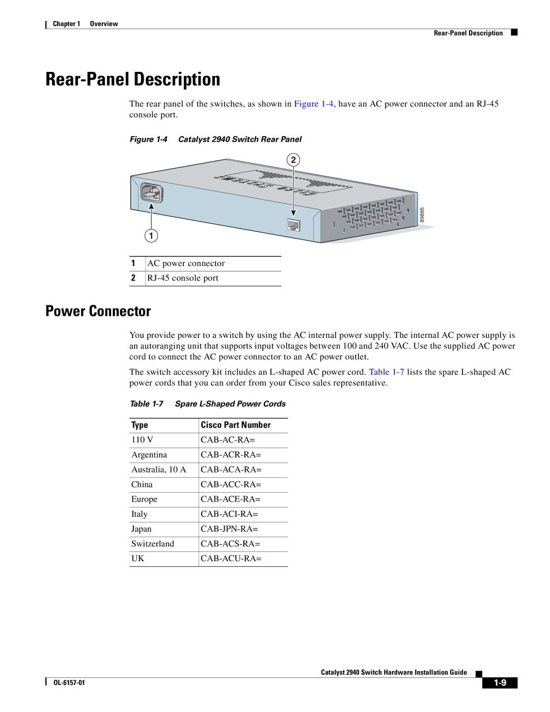
The rear panel of the switches, as shown in Figure
Figure 1-4 Catalyst 2940 Switch Rear Panel
2
1
2
1
AC power connector
 89886
89886
Power Connector
You provide power to a switch by using the AC internal power supply. The internal AC power supply is an autoranging unit that supports input voltages between 100 and 240 VAC. Use the supplied AC power cord to connect the AC power connector to an AC power outlet.
The switch accessory kit includes an
Table
Type | Cisco Part Number |
|
|
110 V | |
|
|
Argentina | |
|
|
Australia, 10 A | |
|
|
China | |
|
|
Europe | |
|
|
Italy | |
|
|
Japan | |
|
|
Switzerland | |
|
|
UK |
|
|
|
Catalyst 2940 Switch Hardware Installation Guide
|
| ||
|
|