A P P E N D I X B
Connectors and Cables
This appendix describes the connectors, cables, and adapters that you use to connect the switch to other devices.
Connector Specifications
These sections describe the connectors used with the Catalyst 2940 switches and contains this information:
•10/100 Ports, page
•10/100/1000 Ports, page
•
•SFP Module Slot, page
•Console Port, page
10/100 Ports
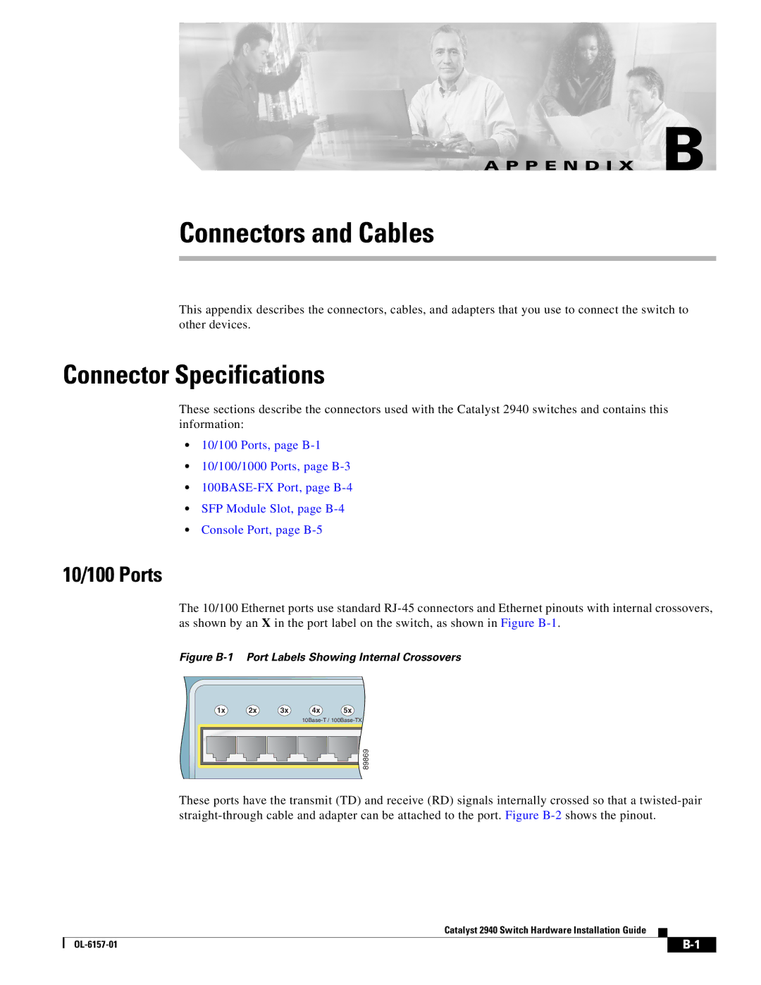
The 10/100 Ethernet ports use standard
Figure B-1 Port Labels Showing Internal Crossovers
1x | 2x | 3x | 4x | 5x |
![]() 89869
89869
These ports have the transmit (TD) and receive (RD) signals internally crossed so that a
Catalyst 2940 Switch Hardware Installation Guide
| ||
|