Appendix B Connectors and Cables
Cable and Adapter Specifications
Cable and Adapter Pinouts
This section describes the cable and adapter pinouts and also describes how to identify a rollover cable.
Connecting to a PC
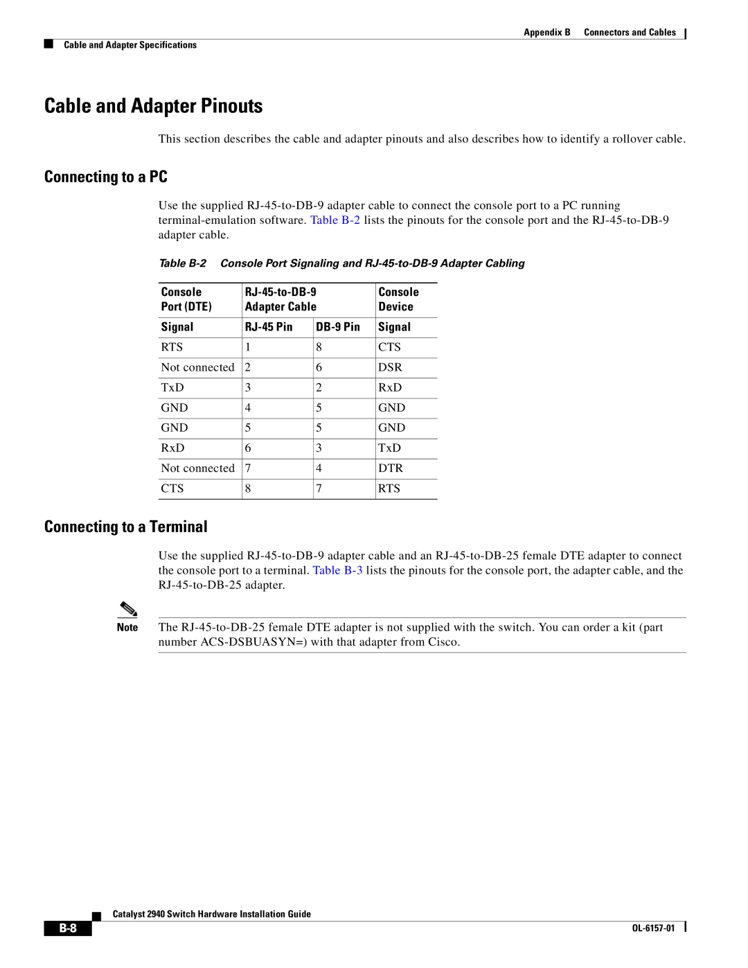
Use the supplied RJ-45-to-DB-9 adapter cable to connect the console port to a PC running terminal-emulation software. Table B-2lists the pinouts for the console port and the RJ-45-to-DB-9 adapter cable.
Table B-2 Console Port Signaling and RJ-45-to-DB-9 Adapter Cabling
Console | RJ-45-to-DB-9 | Console |
Port (DTE) | Adapter Cable | Device |
| | | |
Signal | RJ-45 Pin | DB-9 Pin | Signal |
| | | |
RTS | 1 | 8 | CTS |
| | | |
Not connected | 2 | 6 | DSR |
| | | |
TxD | 3 | 2 | RxD |
| | | |
GND | 4 | 5 | GND |
| | | |
GND | 5 | 5 | GND |
| | | |
RxD | 6 | 3 | TxD |
| | | |
Not connected | 7 | 4 | DTR |
| | | |
CTS | 8 | 7 | RTS |
| | | |
Connecting to a Terminal
Use the supplied RJ-45-to-DB-9 adapter cable and an RJ-45-to-DB-25 female DTE adapter to connect the console port to a terminal. Table B-3lists the pinouts for the console port, the adapter cable, and the RJ-45-to-DB-25 adapter.
Note The RJ-45-to-DB-25 female DTE adapter is not supplied with the switch. You can order a kit (part number ACS-DSBUASYN=) with that adapter from Cisco.
Catalyst 2940 Switch Hardware Installation Guide