Cisco Systems, Inc 170 West Tasman Drive San Jose, CA
Catalyst 2940 Switch Hardware Installation Guide
November
800 553-NETS Fax 408
Catalyst 2940 Switch Hardware Installation Guide
Turn the television or radio antenna until the interference stops
Purpose
C O N T E N T S
Preface
TAC Case Priority Definitions
Troubleshooting
Installation
Where to Go Next
Understanding POST Results Diagnosing Common Problems
IP Settings D-5
Configuring the Switch with the CLI-Based Setup Program D-1
Accessing the CLI Through the Console Port D-2
Where to Go Next D-8
Contents Catalyst 2940 Hardware Installation Guide
OL-6157-01
Purpose
Preface
Audience
Conventions
viii
Warning IMPORTANT SAFETY INSTRUCTIONS
Avvertenza IMPORTANTI ISTRUZIONI SULLA SICUREZZA
Preface Conventions Catalyst 2940 Switch Hardware Installation Guide
OL-6157-01
Este símbolo de aviso significa perigo. Você se encontra em uma situação em que há risco de lesões corporais. Antes de trabalhar com qualquer equipamento, esteja ciente dos riscos que envolvem os circuitos elétricos e familiarize-se com as práticas padrão de prevenção de acidentes. Use o número da declaração fornecido ao final de cada aviso para localizar sua tradução nos avisos de segurança traduzidos que acompanham o dispositivo
Preface Conventions Catalyst 2940 Switch Hardware Installation Guide
OL-6157-01
Related Publications
xiii
Documentation CD-ROM
Obtaining Documentation
Cisco.com
Ordering Documentation
Cisco TAC Website
Obtaining Technical Assistance
Documentation Feedback
Opening a TAC Case
Obtaining Additional Publications and Information
TAC Case Priority Definitions
xvii
Internet Protocol Journal is a quarterly journal published by Cisco Systems for engineering professionals involved in designing, developing, and operating public and private internets and intranets. You can access the Internet Protocol Journal at this URL
Preface Obtaining Additional Publications and Information
xviii
Catalyst 2940 Switch Hardware Installation Guide
OL-6157-01
Setting up the Switch, page Features, page
Setting up the Switch
Features
Setup Program.”
Figure 1-1 and Figure 1-2 show the switches
Front-Panel Description
10/100/1000 Port
Port Numbering
10/100 Ports
Port or Slot type
Type
100BASE-FX Port
SFP Module Slot
Cisco Part Number
SFP Modules
Table 1-3 Cabling Stipulations for Fiber-Optic SFP Modules
Cable Guard
LEDs
Mode LED
SYST LED
STAT, DPLX, SPD, and Port LEDs
Port Mode
Meaning
Port Mode
Color
Table 1-6 Meaning of Port LED Colors in Different Modes
Power Connector
Rear-Panel Description
1-10
Console Port
Security Slots
Management Options
1-11
Chapter 1 Overview Management Options
1-12
Catalyst 2940 Switch Hardware Installation Guide
OL-6157-01
Preparing for Installation, page Verifying Switch Operation, page
Installation
Preparing for Installation
Installing the Switch, page Connecting to an SFP Module, page
Warning Class 1 laser product. Statement
Installation Guidelines
Verifying Package Contents
Verifying Switch Operation
Table 2-1 MT-RJ Patch Cables for 100BASE-FX Connections
Installing the Switch on a Desk With Mounting Screws
Installing the Switch
Installing the Switch on a Desk Without Mounting Screws
“Installing the Switch Under a Desk” section on page
Screw template
Installing the Switch Under a Desk
Figure 2-2 Mounting the Switch on Top of a Desk
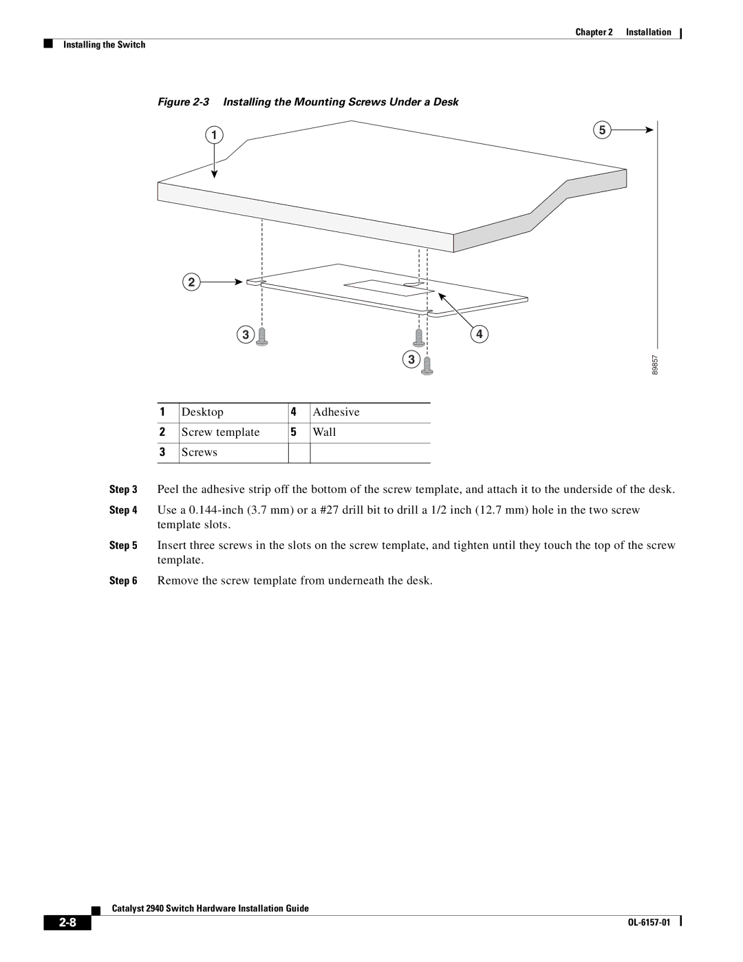
Figure 2-3 Installing the Mounting Screws Under a Desk
Slides on this way
Installing the Switch on a Wall
Desktop
Screws
SIDE
2-10
THIS
CABLE
Chapter 2 Installation Installing the Switch
2-11
Figure 2-6 Installing the Switch On a Wall
Catalyst 2940 Switch Hardware Installation Guide
2-12
Connecting to an SFP Module
Installing the Switch Magnet Mount
2-13
Follow these steps to connect a fiber-optic cable to an SFP module
Connecting to 10/100 Ports and the 10/100/1000 Port
2-14
Figure 2-10 Connecting to a 100BASE-FX Port
Connecting to the 100BASE-FX Port
2-15
Figure 2-11 Connecting to an SFP Module Port
2-16
Connecting to an SFP Module
Where to Go Next
2-17
Installation
2-18
Where to Go Next Catalyst 2940 Switch Hardware Installation Guide
Chapter
Understanding POST Results, page Diagnosing Common Problems, page
Troubleshooting
Diagnosing Common Problems
Understanding POST Results
No connectivity to 10/100 ports
Specifications” section on
Note See the “Connecting to
Incorrect or bad cable
errdisable recovery cause
Switch placed in
error-disabled state after SFP
recovery command
Cabling distance exceeded
errors
Poor performance or excessive
Bad adapter in attached
Corrupted software
System LED is amber
and all port LEDs are
System LED is amber
OL-6157-01
Chapter 3 Troubleshooting Diagnosing Common Problems
Catalyst 2940 Switch Hardware Installation Guide
Technical Specifications
A P P E N D I X A
Table A-3 Catalyst 2940 Switch Agency Approvals
Catalyst 2940 Switch Hardware Installation Guide
Table A-3 Catalyst 2940 Switch Agency Approvals continued
Appendix A Technical Specifications
EN61000-4-11/IEC1000-4-11 Immunity to Voltage
OL-6157-01
Appendix A Technical Specifications
Catalyst 2940 Switch Hardware Installation Guide
A P P E N D I X B
Connectors and Cables
Connector Specifications
10/100 Ports, page B-1 10/100/1000 Ports, page B-3
Figure B-2 10/100 RJ-45 Pinouts
10/100/1000 Ports
Connecting to 10BASE-T and 100BASE-TX Devices
Connecting to 1000BASE-T Devices
100BASE-FX Port
Figure B-4 MT-RJ Connector
Figure B-5 SFP Module Connector
SFP Module Slot
Two Twisted-Pair Cable Pinouts, page B-5
Cable and Adapter Specifications
Two Twisted-Pair Cable Pinouts
Four Twisted-Pair Cable Pinouts for 10/100 Ports, page B-6
Four Twisted-Pair Cable Pinouts for 10/100 Ports
Four Twisted-Pair Cable Pinouts for 1000BASE-T Ports
Cable and Adapter Pinouts
Connecting to a PC
Connecting to a Terminal
Identifying a Rollover Cable
Catalyst 2940 Switch Hardware Installation Guide
B-10
Appendix B Connectors and Cables Cable and Adapter Specifications
OL-6157-01
Methods for Accessing the CLI, page C-1
Configuring the Switch with the CLI-Based Setup Program
Methods for Accessing the CLI
Connecting to a Power Source, page C-3
Accessing the CLI Through the Console Port
Taking Out What You Need
Connecting to a Power Source
Connecting to the Console Port
Starting the Terminal Emulation Software
Entering the Initial Configuration Information
IP Settings
Completing the Setup Program
Page
Where to Go Next
IN-1
Numerics
I N D E
IN-2
IN-3
speed LED
software switch management
specifications A-1 to A-2
stacking the chassis warning
temperature
technical specifications A-1 to A-2
Telnet, and accessing the CLI
terminal, connecting to a switch B-8 to B-9
OL-6157-01
IN-6
Index Catalyst 2940 Switch Hardware Installation Guide