Chapter 2 Installation
Connecting to the
Step 2 Insert the other cable end into an
Step 3 Observe the port status LED.
The LED turns green when the switch and the target device have an established link.
The LED turns amber while Spanning Tree Protocol (STP) discovers the network topology and searches for loops. This process takes about 30 seconds, and then the LED turns green.
If the LED is off, the target device might not be turned on, there might be a cable problem, or there might be a problem with the adapter installed in the target device. See Chapter 3, “Troubleshooting,” for solutions to cabling problems.
Step 4 Reconfigure and restart the target device if necessary.
Step 5 Repeat Steps 1 through 4 to connect each port.
Connecting to the 100BASE-FX Port
The
You can connect a
Caution Do not remove the dust plugs from the
Follow these steps to connect the switch to a
Step 1 Remove the dust plugs from the
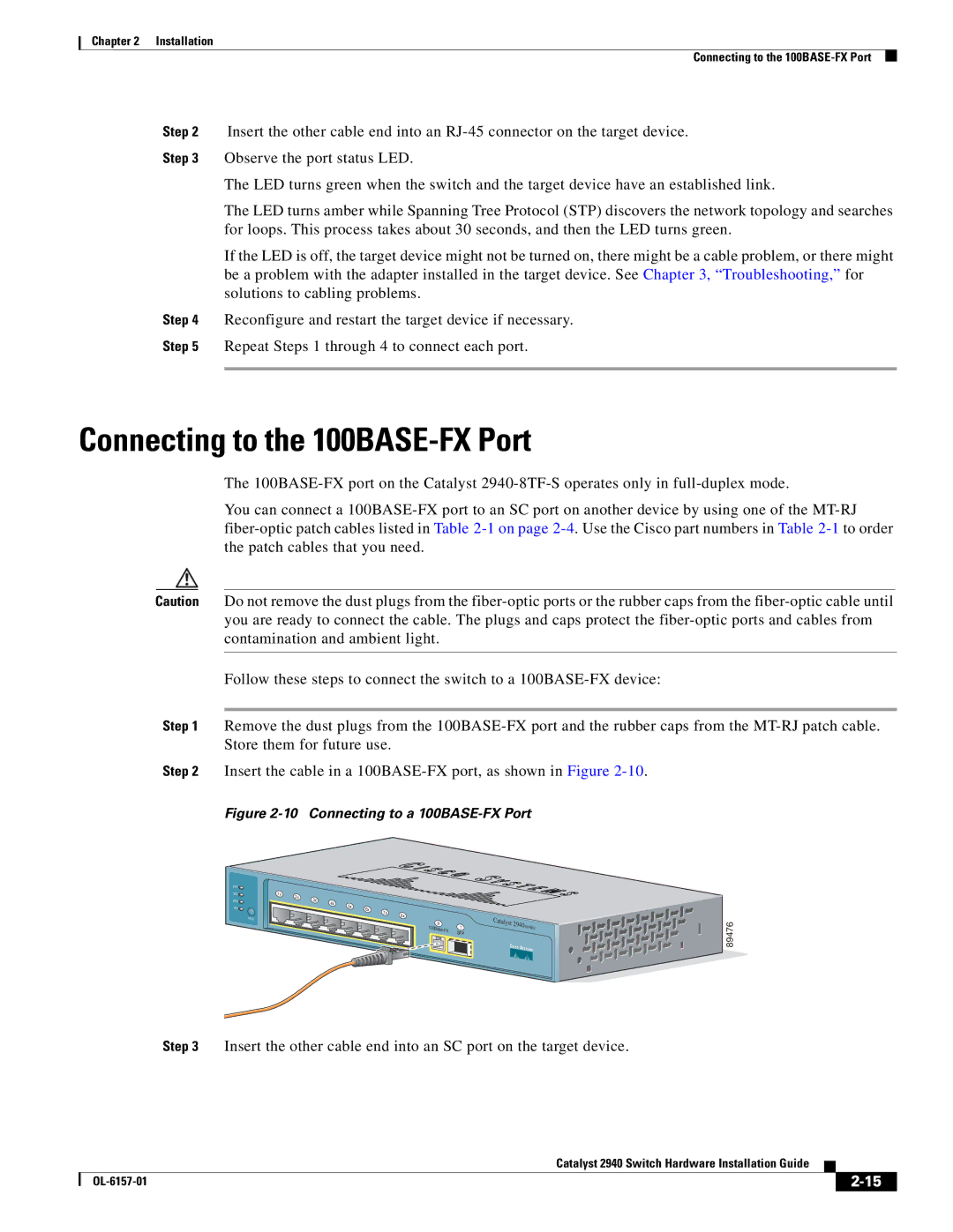
Step 2 Insert the cable in a
Figure 2-10 Connecting to a 100BASE-FX Port
SYST![]()
STAT![]()
DPLX![]()
SPD![]()
MODE
1x | 2x |
|
|
|
|
|
|
| 3x |
|
|
|
|
| |
|
| 4x |
|
|
|
| |
|
|
| 5x |
|
|
| |
|
|
|
| 6x |
|
| |
|
|
|
|
| 7x |
| |
|
|
|
|
|
| 8x | |
|
|
|
|
|
|
|
9 | 1 | |
SFP | ||
|
Catalyst
2940 | SERIES |

![]()
![]()
![]()
![]()
![]()
![]()
![]()
![]()
![]()
![]()
![]()
![]()
![]()
![]()
![]()
![]() 89476
89476
Step 3 Insert the other cable end into an SC port on the target device.
Catalyst 2940 Switch Hardware Installation Guide
|
| ||
|
|