Maintenance & Service Guide
Compaq Deskpro EP Series of Personal Computers
Guide to Features & Upgrades
Compaq Deskpro EP Series of Personal Computers
Maintenance & Service Guide
Compaq Deskpro EP Series of Personal Computers
Compaq Computer Corporation
CONTENTS
Removal and Replacement Preliminaries
preface
About This Guide
Removal and Replacement Procedures
iv Contents
chapter
Connectors, Jumpers, and Switches
Specifications
Service Notes
chapter
Symbols and Conventions
preface
ABOUT THIS GUIDE
Technician Notes
Locating Additional Documentation
Compaq Service Advisories and Bulletins Compaq QuickFind
Technical Reference Guide Compaq Service Quick Reference Guide
The following documentation is available to support these products
chapter
PRODUCT DESCRIPTION
Compaq Deskpro EP Series of Personal Computers
1.1 Model Overview
1.2 System Design
1.3 Preinstalled Software
1.3.1 Ordering Additional Software
Online Safety & Comfort Guide English only
1.4 Computer Features
1.4.1 Front Panel Controls and LEDs - 440BX
1.4.2 Front Panel Controls and LEDs - Intel 810/810e
Front Panel Controls and LEDs - Intel 810/ 810e
Component/Function
Component/Function
1.4.3 Rear Panel Connectors - 440BX
Rear Panel Connectors - 440BX
Component
Component
1.4.4 Rear Panel Connectors - Intel 810/810e
Rear Panel Connectors - Intel 810/810e
Component
Component
1.4.5 Drive Positions
Configuration
Drive bay numbers are stamped on the chassis
Drive Positions
1.5 Serial Number Location
Serial Number Locations
chapter
SPARE PARTS
2.1 System Unit
2.1.1 System Unit - 440BX
System Unit Spare Parts - 440BX Model
2-2 Spare Parts
System Unit Spare Parts - 440BX
Major Differences Between 440BX and Intel 810/810e
Compaq Despro EP Series of Personal Computers
2.1.2 System Unit - Intel 810/810e
System Unit Spare Parts - Intel 810/810e Model
2-4 Spare Parts
System Unit Spare Parts - Intel 810/810e
Major Differences Between 440BX and Intel 810/810e
2.2 Mass Storage Devices
Mass Storage Devices
2-6 Spare Parts
Mass Storage Devices
2.3 Cables
Cables
2-8 Spare Parts
Cables
Description
Spare Part Number
Cable Kit includes
2.4 Standard and Optional Boards
Standard and Optional Boards
2-10 Spare Parts
Standard and Optional Boards
Not shown
Standard and Optional Boards, continued
2-12 Spare Parts
Standard and Optional Boards Continued
Compaq Despro EP Series of Personal Computers
and thermal interface. Use on 010697-101 system board
Standard and Optional Boards Continued
PREMIER ∙SOUND 440BX
Compaq PREMIER ∙SOUND board
2-14 Spare Parts
2.5 Keyboards
Keyboards
Compaq Despro EP Series of Personal Computers
2.6 Miscellaneous Hardware Kit
Miscellaneous Hardware
Miscellaneous Hardware Kit
2-16 Spare Parts
2.7 Miscellaneous Plastics Kit
Miscellaneous Plastics Kit, Desktop and Minitower
Miscellaneous Plastics Kit
Compaq Despro EP Series of Personal Computers
2.8 Miscellaneous Parts
Miscellaneous Parts
Miscellaneous Parts
2-18 Spare Parts
2.9 Shipping Boxes
2.10 Documentation and Software
Shipping Boxes not illustrated
Documentation and Software not illustrated
REMOVAL AND REPLACEMENT PRELIMINARIES
3.1.1 Cleaning Safety Precautions
3.1.2 Cleaning the Computer Case
3.1 Routine Care
3.1.3 Cleaning the Keyboard
3.1.4 Cleaning the Monitor
3.1.5 Cleaning the Mouse
3.2 Electrostatic Discharge Information
3.2.1 Generating Static
3.2.2 Preventing Electrostatic Damage to Equipment
3.2.3 Personal Grounding Methods and Equipment
3.2.4 Grounding Workstations
3.2.5 Recommended Materials and Equipment
Static Shielding Protection Levels
3.3 Service Considerations
3.3.3 Cables and Connectors
3.3.1 Tools and Software Requirements
3.3.2 Screws
3.3.4 Hard Drives
3.3.5 Plastic Parts
REMOVAL AND REPLACEMENT PROCEDURES
4.1 Disassembly Sequence Chart
chapter
4.2 Disassembly Preparation
4.3 Feet Installation
Installing the Feet
4.4 Logo Plate
Replacing the Compaq Logo Plate
4.5 Cable Lock
To remove the cable lock provision, reverse the above procedure
Installing the Cable Lock Provision - Intel 810/810e
4-6 Removal and Replacement Procedures
4.6 Access Panel
4.7 Front Bezel
Removing the Front Bezel
4.8 Power Button
Removing the Power Button
4.9 Subpanel and Bezel Blanks
Removing the Subpanel and Bezel Blanks
4.10 Power Switch
Disconnecting the Power Switch
4.11 Mass Storage Devices
Drive Positions
Using the Cable-Select Feature with Ultra ATA Devices
4.11.1 Removing an Internal 3.5-Inch Hard Drive
Disconnecting the Cables
Unlocking the Drives
8. Remove the four guide screws from the drive
4.11.2 Removing an External 5.25-Inch Drive
Releasing the Drives
Removing an External 5.25-inch Drive
4.11.3 Removing an External 3.5-Inch Drive
4-18 Removal and Replacement Procedures
8. Remove the drive bezel
To replace the drive, reverse the previous procedures
4.12 Removing the Drivelocks
Drivelock Mechanism
4-21
Compaq Deskpro EP Series of Personal Computers
4-22 Removal and Replacement Procedures
Removing the Drivelock Mechanism
11. Remove the spring from the post see inset
4.13 Expansion Boards
4.13.1 440BX
4-24 Removal and Replacement Procedures
Deskpro EP Expansion Slots - 440BX 2-DIMM Model
4.13.2 Intel 810 and 810e
Deskpro EP Expansion Slots - Intel
Deskpro EP Expansion Slots - Intel 810e
4-25
4.13.3 Removing an Expansion Board
Removing the Expansion Board
4.13.4 Installing an Expansion Board
Removing the Expansion Board Slot Cover
6. Secure the board to the chassis with the retaining screw
4.14 Board Guide
Removing the Board Guide
4.15 System Memory
4.15.1 440BX
4.15.2 Intel 810/810e
Installing a DIMM Module
4.16 AGP Graphics Board 440BX
4.16.1 AGP Graphics Board Removal 440BX
4.16.2 Graphics Memory Upgrade 440BX
Installing the Memory Module
4.17 Processor Components
4.17.1 Processor
To install a new processor, reverse this procedure
4-36 Removal and Replacement Procedures
4.17.2 Processor Guide Rails
Removing the Processor Rails
Reinstall the system board in the computer chassis
4.18 System Board
Removing the System Board
4.19 Internal Speaker
Removing the Speaker From the Side of the Drive Cage
To install the new speaker, reverse the preceding steps
Removing the Speaker From the Rear of the Chassis
4-41
Compaq Deskpro EP Series of Personal Computers
4.20 Lithium Battery
Locating the Battery on the System Board - 440BX
Locating the Battery on the System Board - Intel
Locating the Battery on the System Board - Intel 810e
4-43
Compaq Deskpro EP Series of Personal Computers
5. Lift the battery out of the holder
4.21 Fan Assembly
Removing the Fan
4.22 Power Supply
Removing the Power Supply - 440BX
To replace the power supply, reverse the above procedure
Removing the Power Supply - Intel 810/810e
4-47
Compaq Deskpro EP Series of Personal Computers
4.23 Converting a Desktop to a Minitower
Activating the Drivelocks Shown from the Rear of the Chassis
Installing a Drive in the Minitower Configuration
7. Reconnect the power, signal, and audio cables to the drives
4.24 Converting a Minitower to a Desktop
Installing a Drive in the Desktop Configuration
4-52 Removal and Replacement Procedures
8. Reconnect the power, signal, and audio cables to the drives
CONNECTORS, JUMPERS, AND SWITCHES
5.1.1 Connectors, Jumpers, and Switches
Connectors, Jumpers, and Switches - 440BX Three-DIMM Board
5.1 System Board
Connectors, Jumpers, and Switches - 440BX Two-DIMM Board
Connectors, Jumpers, and Switches - Intel 810e PCA=010697-101
5-2 Connectors, Jumpers, and Switches
System Board Overview - 440BX Two-DIMM Board
Connectors, Jumpers, and Switches - Intel 810/810e Two-DIMM Board
System Board Overview - Intel 810 Two-DIMM Board
System Board Overview - Intel 810e Two-DIMM Board
Description
5.1.2 Switches
Switch SW1 Settings 440BX
5.1.3 Jumpers 440BX
E50 Jumper Location
Disabling or Clearing the Power-On and Setup Passwords 440BX
Clearing Configuration Memory CMOS 440BX
5-6 Connectors, Jumpers, and Switches
5.1.4 Jumpers Intel 810/810e
E49 Jumper Location
Disabling or Clearing the Power-On and Setup Passwords Intel 810/810e
5-8 Connectors, Jumpers, and Switches
Clearing Configuration Memory CMOS - Intel 810/810e
CMOS Button SW50 Location
5.2.1 Using the Cable-Select Feature with Ultra ATA Devices
5.2 Hard Drives
5.2.2 Drive Jumper Settings
Definition
Seagate
Fujitsu
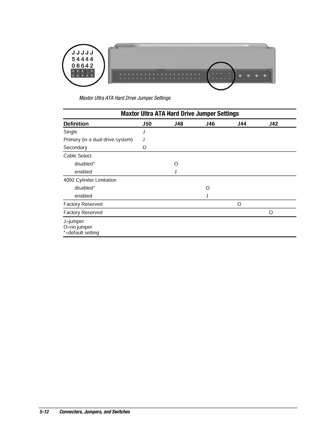
Maxtor Ultra ATA Hard Drive Jumper Settings
5-12 Connectors, Jumpers, and Switches
Definition
SPECIFICATIONS
6.1 Specifications
System
6.1.1
Interrupts
6.1.2
6-2 Specifications
Hardware IRQ
6.1.4 I/O
6.1.3
System Function Shipping Configuration
Hardware DMA
System Function Shipping Configuration
6-4 Specifications
I/O Address Hex
I/O Continued
6.2 Drives
6.1.5 Memory Map
1.44-MB Diskette Drive
6.2.1
6.2.2
6-6 Specifications
Ultra ATA Hard Drives
3.2-GB
6.2.3 CD-ROM Drives
24X Max
32X Max
6-8 Specifications
CD-ROM continued
40X Max
6.5 Supported Graphics Resolutions
6.3 Compaq Enhanced Keyboard
6.4 2-Button Mouse
6.5.1 ATI RAGE PRO TURBO 1X AGP
6.5.2 ATI RAGE PRO IIC AGP
6.5.3 NVIDIA RIVA 128 AGP
6.5.4 Matrox MGA G100 AGP
6-10 Specifications
6.5.5 Matrox Millenium G200-SD AGP
6.5.6 Matrox Millenium G400-SG AGP
6.5.7 Integrated Intel 3D Graphics
6.6 Audio Controllers
6-12 Specifications
440BX440BX
Intel 810/810e
6-13
SERVICE NOTES
chapter
Index
Page
system design, 1-3 specifications system board
tools service considerations
Ultra ATA devices, 4-13 Ultra ATA hard drive specifications
Western Digital EIDE hard drive jumper settings
181099-001
134011-004