User’s Guide
Order Number EK-GS320-UG. B01
Compaq Computer Corporation
First Printing, May
Contents
GS80 Rack System Overview
GS160/320 System Configuration Rules
GS80 Rack System Configuration Rules
Booting and Installing an Operating System
Using the System Control Manager
Chapter Operation
Appendix a Jumpering Information
Figures
Glossary Index Examples
Vii
Tables
Viii
Preface
Intended Audience
Document Structure
Order Number Title
AlphaServer 80/160/320 Family Documentation
Documentation Titles
Information on the Internet
Introduction
Chapter Introduction
AlphaServer GS80/160/320 User’s Guide
AlphaServer GS160/320 and GS80 Systems
AlphaServer GS160/320 System
AlphaServer GS80 System
System Management Console
System Control Manager SCM
LFU Loadable Firmware Update Utility
Firmware and Utilities Overview
SRM Console
Sample System Architecture
System Architecture
Page
GS160/320 System Overview
Chapter GS160/320 System Overview
Specification
System Characteristics
System Box Characteristics
Characteristic
Environmental
Power Cabinet and System Environmental Characteristics
Power Cabinet Electrical
Specifications
System Box Architecture
System Box Block Diagram 16-Processor System
System Box Block Diagram 8-Processor System
Shows two QBBs back to back in the system box
Quad Building Block QBB Components
GS160/320 System Overview
Backplane System Box, Front View
Backplane
GS160/320 System Overview
CPU Module
CPU Module
Memory Module
Memory Module
Directory Module
Directory Module
Power Modules
Power Modules
10 Power System Manager Module
Power System Manager Module
11 Clock Splitter Module
Clock Splitter Module
12 I/O Riser Module
8 I/O Riser Module
13 Global Port Module
Global Port Module
14 Distribution Board
Distribution Board
15 Distribution Board in Single-Box System
16 Hierarchical Switch
Hierarchical Switch
GS160/320 System Overview
17 Power System
Power System
GS160/320 System Overview
18 AC Input Box
AC Input Box
Circuit Breaker Lines Protected
AC Input Box Circuit Breakers
19 PCI Master Box
PCI I/O
BA54A-BA PCI Box
BA54A-AA PCI Box
20 Control Panel
Control Panel
GS160/320 System Overview
21 shows the various control panel LED status indications
Control Panel LEDs
GS160/320 System Configuration Rules
GS160 System
GS160 System Cabinet
About the System Cabinet
GS160 Configuration Rules
GS320 System
GS320 System Cabinets
GS320 System Configuration Rules
Power Cabinet Configuration 32-P System
Power Cabinet
Power System Requirements
Show the power supply slot assignments in each power subrack
Power Supply Slot Assignments
Power Supply Configuration Rules
System Box QBB Cabinet Front
System Box
System Box QBB Cabinet Rear
System Box Configuration Rules
QBB Center Bar Color Code Cabinet Front
QBB Color Code
QBB Center Bar Color Code Cabinet Rear
Memory Module and Directory Module
Memory Configurations
Directory Dimm Type Memory Array Size Part Number
Memory Configuration Guidelines
Guidelines
Memory Interleaving Guidelines
Interleaving Memory Modules
Memory Interleaving
Memory Interleaving Guidelines
10 Sample I/O Subsystem
PCI Boxes
GS160/320 System Configuration Rules
11 PCI Slot Locations
PCI Box Slot Configuration
Remote I/O Riser Logical Hose
PCI Slot Configuration Guidelines
PCI Slots and Logical Hoses
Logical Hoses
Expander Cabinet
12 BA356 Storage Device Configurations
GS80 Rack System Overview
Chapter GS80 Rack System Overview
Rack System Characteristics
System Drawer Characteristics
Characteristic Specification
Rack System Characteristics
System Drawer Architecture
Two-Drawer Block Diagram
GS80 Rack System Overview
System Drawer Modules
System Drawer Modules
System Drawer Backplane
Page
GS80 Rack System Configuration Rules
GS80 Rack System Configuration Rules
Rack houses a maximum of two system drawers
Rack
Rack Variants
About the Rack Cabinet
Two-Drawer Rack Power System
Rack Power System
About the Power System
Page
Booting and Installing an Operating System
Chapter Booting and Installing an Operating System
Powering Up the System
SCM Power-Up Display
Example 6-1 SCM Power-Up Display
On next
QBB0
Box-0
Example 6-2 SRM Power-Up Display
SRM Power-Up Display
On next
Entering idle loop initializing keyboard
Idle process PID
Bootdefdev
Setting Boot Options
Example
Bootfile
Set bootdefdev bootdevice
Set bootfile filename
Set bootosflags flagsvalue
Bootosflags
FlagsValue Bit Number Meaning
OpenVMS Boot Flag Settings
Set ei*0inetinit value or set ew*0inetinit value
4 ei*0inetinit or ew*0inetinit
Bootp
Bootp,mop
5 ei*0protocols or ew*0protocols
Example 6-3 Booting Tru64 Unix from a Local Scsi Disk
Booting Tru64 Unix
Example 6-3 Booting Tru64 Unix from a Local Scsi Disk
Example 6-4 RIS Boot
Booting Tru64 Unix Over the Network
P00 set eia0protocols bootp P00 set eia0inetinit bootp
Example 6-5 Tru64 Unix Installation Display
Installing Tru64 Unix
Booting and Installing an Operating System
Example 6-6 Booting OpenVMS from a Local Disk
Booting OpenVMS
Booting and Installing an Operating System
Example 6-7 InfoServer Boot
Booting OpenVMS from the InfoServer
Function
Example 6-8 OpenVMS Installation Menu
Installing OpenVMS
Booting and Installing an Operating System
Page
Operation
Chapter Operation
SRM Command Overview
Summary of SRM Commands
SRM Console
Command
Notation Formats for SRM Console Commands
Attribute
Conditions
Character
Special Characters for SRM Console
Example 7-1 Set OcpText Command
Setting the Control Panel Message
Displaying the System Configuration
Show Boot Command
Example 7-2 Show Boot
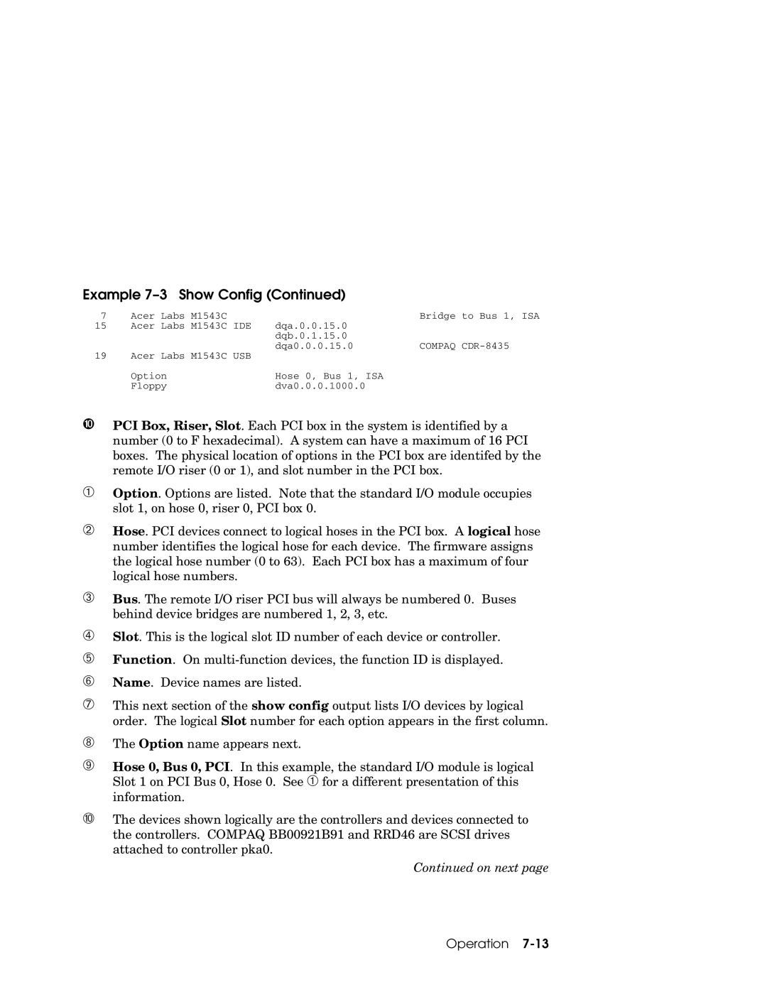
Example 7-3 Show Config
Show Config Command
On next
IOD revs Local Link NE ML rev
Operation
DEGPA-SA
Compaq CDR-8435
RZ1CB-CA
PowerStorm Acer Labs M1543C
Example Show Device
Show Device Command
Category Description
Device Naming Conventions
Show Memory Command
Show memory command displays the main memory configuration
Example Show Memory
Setting SRM Environment Variables
Setting SRM Console Security
Setting Tru64 Unix or OpenVMS Systems to Auto Start
Changing the Default Boot Device
About Soft Partitioning
Soft Partitioning
SRM Environment Variables for Soft Partitions
Environment Variable
Definition
Example 7-6 Defining Soft Partitions
Memory
Instance
Hpcount Hpqbbmaskx
Hard Partitioning
SCM Environment Variables for Hard Partitions
Example 7-7 Defining Hard Partitions
Operation
Page
Using the System Control Manager
Using the System Control Manager
Console Serial Bus Subsystem
CSB Block Diagram
Using the System Control Manager
System Control Manager Overview
Configuration, Error Log, and Asset Information
SCM Firmware
PSMs, PBMs, and HPMs
SCM COM1 Operating Modes
Data Flow in Through Mode
Local Mode
Through Mode
Bypass Modes
Data Flow in Bypass Mode
Soft Bypass Mode
Snoop Mode
Hard Bypass Mode
Firm Bypass Mode
Setups for SCM PCI Box
Console Device Setup
Entering SCM Commands from a VGA Console
Entering the SCM
Entering from a Console Device
SRM Environment Variables for COM1
SCM Commands
SCM Command-Line Interface
SCM Commands
Power-Up Messages
Command Conventions
Defining the COM1 Data Flow
Status Command Fields
Displaying the System Status
Field
Field Meaning
➊ ➋ ➏ ➐ ➑ ➒
Displaying the System Environment
On next
Power On and Power Off
Power On and Off, Reset, and Halt
Halt In and Continue
Reset
Configuring Remote Dial-In
Example 8-1 Dial-In Configuration
Modem Initialization String
Dialing
Example 8-2 Alert Dial-Out Configuration
Configuring Alert Dial-Out
Alert Condition
Elements of Dial String and Alert String
Dial String
Alert String
Resetting the Escape Sequence
Suggested Solution
Troubleshooting Tips
SCM Troubleshooting
Symptom
SCM Troubleshooting
Page
Jumper
Appendix a Jumpering Information
PCI Backplane Jumpers
Table A-1 PCI Backplane Jumpers
Table A-2 HPM Jumpers
Jumper Function, When Installed
HPM Jumpers
Standard I/O Module Jumpers
Glossary
Update Utility Local and remote
Switch Hose
Switch
Switch power
PCI master box
Partition
PCI backplane
Manager PCI expansion box
Module Remote testing
Power cabinet
Power input
Power system
Glossary-5
Vaux
Glossary-6
Index-1
Index
SCM
Index-2
Index-3