Connect Tech Blue Heat/Net Sync User Manual
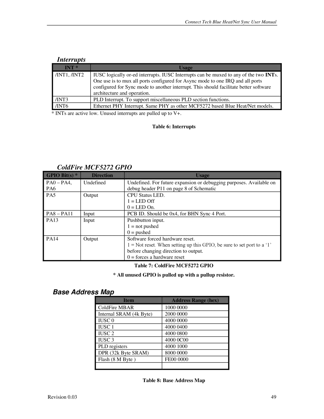
Interrupts
| INT * |
|
| Usage |
|
|
|
|
| ||
| /INT1, /INT2 |
|
| IUSC logically |
|
|
|
|
| One use is to mux all ports configured for Async mode to one IRQ and all ports |
|
|
|
|
| configured for Sync mode to another interrupt. This should facilitate better software |
|
|
|
|
| architecture and operation. |
|
| /INT3 |
|
| PLD Interrupt. To support miscellaneous PLD section functions. |
|
| /INT6 |
|
| Ethernet PHY Interrupt. Same PHY as other MCF5272 based Blue Heat/Net models. |
|
*INTs are active low. Unused interrupts are pulled up to V+.
Table 6: Interrupts
ColdFire MCF5272 GPIO
| GPIO Bit(s) * |
|
| Direction |
|
| Usage |
|
|
|
|
|
|
| |||
PA0 – PA4, |
|
| Undefined |
| Undefined. For future expansion or debugging purposes. Available on |
| ||
PA6 |
|
|
|
| debug header P11 on page 8 of Schematic |
| ||
PA5 |
|
| Output |
| CPU Status LED. |
| ||
|
|
|
|
|
| 1 | = LED Off |
|
|
|
|
|
|
| 0 | = LED On. |
|
PA8 – PA11 |
|
| Input |
| PCB ID. Should be 0x4, for BHN Sync 4 Port. |
| ||
PA13 |
|
| Input |
| Pushbutton input. |
| ||
|
|
|
|
|
| 1 | = not pushed |
|
|
|
|
|
|
| 0 | = pushed |
|
PA14 |
|
| Output |
| Software forced hardware reset. |
| ||
|
|
|
|
|
| 1 | = Not reset. When setting up this GPIO, be sure to set port to a „1‟ |
|
|
|
|
|
|
| before changing direction to output. |
| |
|
|
|
|
|
| 0 | = forces a hardware reset |
|
Table 7: ColdFire MCF5272 GPIO
* All unused GPIO is pulled up with a pullup resistor.
Base Address Map
| Item |
|
| Address Range (hex) |
|
|
|
|
| ||
| ColdFire MBAR |
| 1000 0000 |
| |
| Internal SRAM (4k Byte) |
| 2000 0000 |
| |
| IUSC 0 |
| 4000 0000 |
| |
| IUSC 1 |
| 4000 0400 |
| |
| IUSC 2 |
| 4000 0800 |
| |
| IUSC 3 |
|
| 4000 0C00 |
|
| PLD registers |
| 4000 1000 |
| |
| DPR (32k Byte SRAM) |
| 8000 0000 |
| |
| Flash (8 M Byte ) |
|
| FE00 0000 |
|
|
|
|
|
|
|
Table 8: Base Address Map
Revision 0.03 | 49 |