Connect Tech Blue Heat/Net Sync User Manual
Pinouts
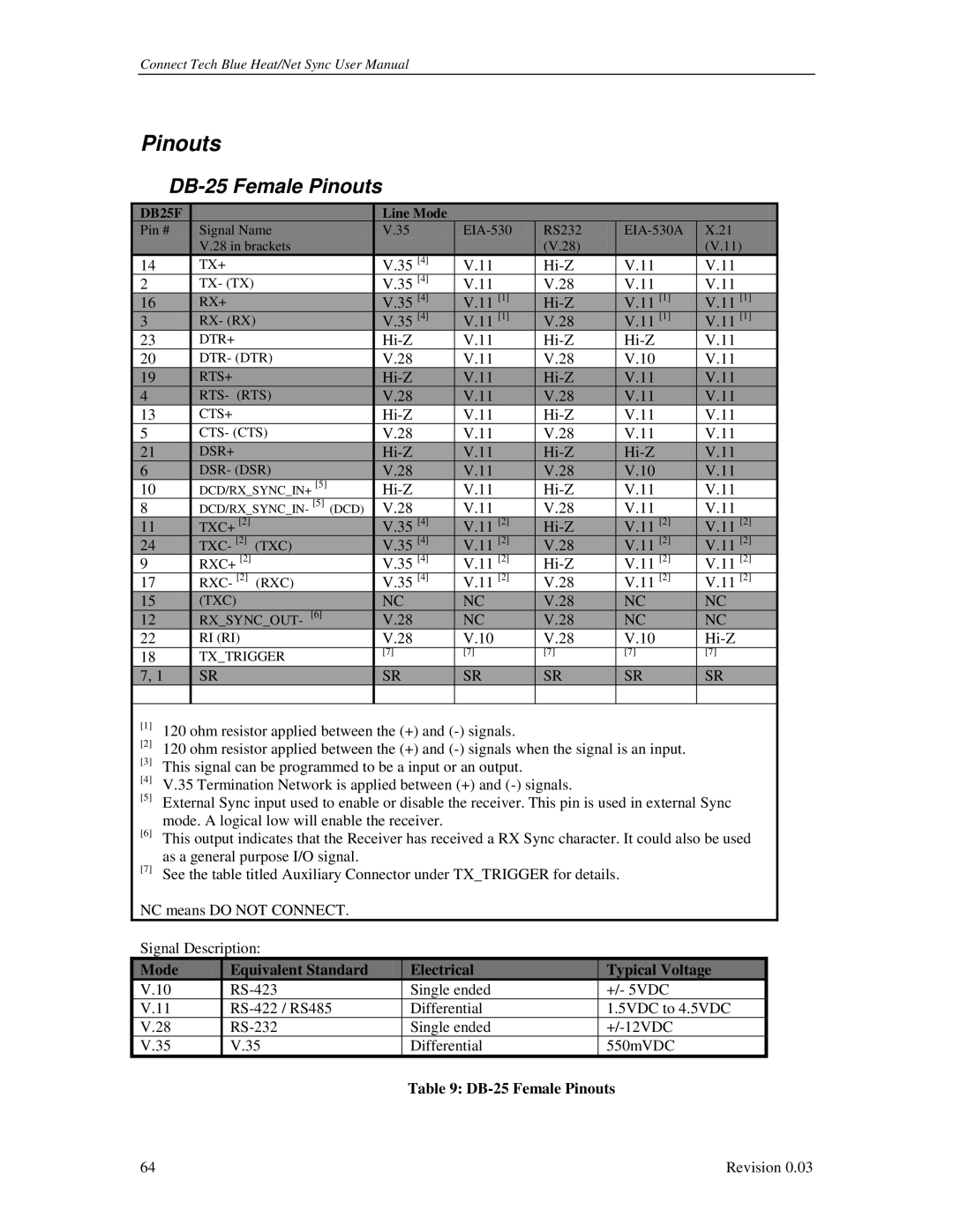
DB-25 Female Pinouts
|
| DB25F |
|
|
|
|
|
| Line Mode |
|
|
|
|
|
| |
|
|
|
|
|
|
|
|
|
|
|
|
|
| |||
|
| Pin # |
|
| Signal Name |
|
| V.35 | RS232 |
| X.21 |
| ||||
|
|
|
|
|
| V.28 in brackets |
|
|
|
| (V.28) |
|
| (V.11) |
| |
| 14 |
|
|
| TX+ |
|
|
| V.35 [4] | V.11 |
| V.11 | V.11 |
| ||
| 2 |
|
|
| TX- (TX) |
|
|
| V.35 [4] | V.11 | V.28 |
| V.11 | V.11 |
| |
|
| 16 |
|
|
| RX+ |
|
|
| V.35 [4] | V.11 [1] |
| V.11 [1] | V.11 [1] |
| |
|
| 3 |
|
|
| RX- (RX) |
|
| V.35 [4] | V.11 [1] | V.28 |
| V.11 [1] | V.11 [1] |
| |
| 23 |
|
|
| DTR+ |
|
|
| V.11 |
| V.11 |
| ||||
| 20 |
|
|
| DTR- (DTR) |
|
| V.28 | V.11 | V.28 |
| V.10 | V.11 |
| ||
|
| 19 |
|
|
| RTS+ |
|
|
| V.11 |
| V.11 | V.11 |
| ||
|
| 4 |
|
|
| RTS- (RTS) |
|
| V.28 | V.11 | V.28 |
| V.11 | V.11 |
| |
| 13 |
|
|
| CTS+ |
|
|
| V.11 |
| V.11 | V.11 |
| |||
| 5 |
|
|
| CTS- (CTS) |
|
| V.28 | V.11 | V.28 |
| V.11 | V.11 |
| ||
|
| 21 |
|
|
| DSR+ |
|
|
| V.11 |
| V.11 |
| |||
|
| 6 |
|
|
| DSR- (DSR) |
|
| V.28 | V.11 | V.28 |
| V.10 | V.11 |
| |
| 10 |
|
|
| DCD/RX_SYNC_IN+ [5] |
|
| V.11 |
| V.11 | V.11 |
| ||||
| 8 |
|
|
| DCD/RX_SYNC_IN- [5] (DCD) |
|
| V.28 | V.11 | V.28 |
| V.11 | V.11 |
| ||
|
| 11 |
|
|
| TXC+ [2] |
|
|
| V.35 [4] | V.11 [2] |
| V.11 [2] | V.11 [2] |
| |
|
| 24 |
|
|
| TXC- [2] | (TXC) |
|
| V.35 [4] | V.11 [2] | V.28 |
| V.11 [2] | V.11 [2] |
|
| 9 |
|
|
| RXC+ [2] |
|
|
| V.35 [4] | V.11 [2] |
| V.11 [2] | V.11 [2] |
| ||
| 17 |
|
|
| RXC- [2] | (RXC) |
|
| V.35 [4] | V.11 [2] | V.28 |
| V.11 [2] | V.11 [2] |
| |
|
| 15 |
|
|
| (TXC) |
|
|
| NC | NC | V.28 |
| NC | NC |
|
|
| 12 |
|
|
| RX_SYNC_OUT- [6] |
|
| V.28 | NC | V.28 |
| NC | NC |
| |
| 22 |
|
|
| RI (RI) |
|
|
| V.28 | V.10 | V.28 |
| V.10 |
| ||
| 18 |
|
|
| TX_TRIGGER |
| [7] | [7] | [7] |
| [7] | [7] |
| |||
|
|
|
|
|
|
|
|
|
|
|
|
| ||||
|
| 7, 1 |
|
| SR |
|
|
| SR | SR | SR |
| SR | SR |
| |
|
|
|
|
|
|
|
|
|
|
|
|
|
|
|
|
|
| [1] | 120 ohm resistor applied between the (+) and |
|
|
|
|
| |||||||||
| [2] | 120 ohm resistor applied between the (+) and |
|
| ||||||||||||
| [3] | This signal can be programmed to be a input or an output. |
|
|
|
|
| |||||||||
| [4] | V.35 Termination Network is applied between (+) and |
|
|
| |||||||||||
| [5] | External Sync input used to enable or disable the receiver. This pin is used in external Sync |
| |||||||||||||
| [6] | mode. A logical low will enable the receiver. |
|
|
|
|
|
| ||||||||
| This output indicates that the Receiver has received a RX Sync character. It could also be used |
| ||||||||||||||
| [7] | as a general purpose I/O signal. |
|
|
|
|
|
|
|
|
| |||||
| See the table titled Auxiliary Connector under TX_TRIGGER for details. |
|
|
| ||||||||||||
NC means DO NOT CONNECT.
Signal Description:
| Mode |
|
| Equivalent Standard |
|
| Electrical |
|
| Typical Voltage |
|
|
|
|
|
|
|
|
| ||||
V.10 |
|
|
|
| Single ended |
|
| +/- 5VDC |
| ||
V.11 |
|
|
|
| Differential |
|
| 1.5VDC to 4.5VDC |
| ||
V.28 |
|
|
|
| Single ended |
|
|
| |||
V.35 |
|
| V.35 |
|
| Differential |
|
| 550mVDC |
| |
Table 9: DB-25 Female Pinouts
64 | Revision 0.03 |