|
|
|
|
|
|
|
|
|
|
|
|
|
|
|
|
| Connect Tech Blue Heat/Net Sync User Manual |
| ||||||||||
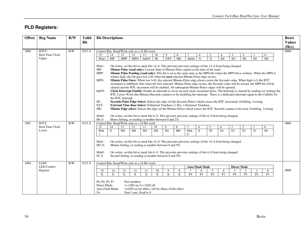
| PLD Registers: |
|
|
|
|
|
|
|
|
|
|
|
|
|
|
|
|
|
|
|
|
|
|
|
|
|
| |
|
|
|
|
|
|
|
|
|
|
|
|
|
|
|
|
|
|
|
|
|
|
|
|
|
|
|
|
|
| Offset | Reg Name | R/W | Valid |
| Bit Descriptions |
|
|
|
|
|
|
|
|
|
|
|
|
|
|
|
|
|
|
| Reset | ||
|
|
|
| Bit |
|
|
|
|
|
|
|
|
|
|
|
|
|
|
|
|
|
|
|
|
|
|
| Values |
|
|
|
|
|
|
|
|
|
|
|
|
|
|
|
|
|
|
|
|
|
|
|
|
|
|
|
| (Hex) |
| 1000 | RTCU | R/W | D15..0 |
| Control Bits: Read/Write only as a 16 Bit word. |
|
|
|
|
|
|
|
|
|
|
|
|
|
|
| 0000 | ||||||
|
| Real Time Clock |
|
|
| 15 | 14 | 13 | 12 |
| 11 | 10 | 9 | 8 | 7 | 6 | 5 | 4 | 3 |
|
| 2 | 1 |
| 0 |
|
|
|
|
| Upper |
|
|
| Msk1 | MP | MPP | MPO |
| IntEN | SE | EXT | ME | Msk0 | X | X | H4 | H3 |
| H2 | H1 |
| H0 |
|
| ||
|
|
|
|
|
| Msk1: | On writes, set this bit to mask bits 14..8. This prevents previous settings of bits 14..8 from being changed. |
|
|
|
|
|
|
| ||||||||||||||
|
|
|
|
|
| MP: | Minute Pulse (read only): Current State of |
|
|
|
|
|
|
|
|
|
| |||||||||||
|
|
|
|
|
| MPP: | Minute Pulse Pending (read only): This bit is set to the same state as the MPO bit (when the MPO bit is written). When the MPO is |
| ||||||||||||||||||||
|
|
|
|
|
|
| written high, this bit goes low (=0) when the next selected |
|
|
|
|
|
|
|
|
|
|
| ||||||||||
|
|
|
|
|
| MPO: | Minute Pulse Once: When low (=0), the selected |
| ||||||||||||||||||||
|
|
|
|
|
|
| increment is inhibited, then when the first selected |
| ||||||||||||||||||||
|
|
|
|
|
|
| cleared and the RTC increment will be enabled. All subsequent |
|
|
|
|
|
|
| ||||||||||||||
|
|
|
|
|
| IntEN: | Clock Interrupt Enable: Enable an interrupt to occur on each clock increment pulse. The Interrupt is cleared by reading (or writing) the |
| ||||||||||||||||||||
|
|
|
|
|
|
| RTC Lower Word (the Minutes/Seconds counter) or by disabling the interrupt. There is a dedicated interrupt signal to the Coldfire for |
| ||||||||||||||||||||
|
|
|
|
|
|
| the RTC interrupt. |
|
|
|
|
|
|
|
|
|
|
|
|
|
|
|
|
|
| |||
|
|
|
|
|
| SE: |
|
|
|
| ||||||||||||||||||
|
|
|
|
|
| EXT: | External Time Base Select: 0=Internal Timebase (1 Hz), 1=External Timebase. |
|
|
|
|
|
|
|
|
|
|
| ||||||||||
|
|
|
|
|
| ME: | Minute Edge select: Selects the edge (of the |
| ||||||||||||||||||||
|
|
|
|
|
| Msk0: | On writes, set this bit to mask bits 6..0. This prevents previous settings of bits 6..0 from being changed. |
|
|
|
|
|
|
| ||||||||||||||
|
|
|
|
|
| H4..0 | Hours Setting, or reading (a number between 0 and 23). |
|
|
|
|
|
|
|
|
|
|
|
|
|
| |||||||
| 1002 | RTCL | R/W | D15..0 |
| Control Bits: Read/Write only as a 16 Bit word. |
|
|
|
|
|
|
|
|
|
|
|
|
|
|
| 0000 | ||||||
|
| Real Time Clock |
|
|
| 15 | 14 | 13 | 12 |
| 11 | 10 | 9 | 8 | 7 | 6 | 5 | 4 | 3 |
|
| 2 | 1 |
| 0 |
|
|
|
|
| Lower |
|
|
| Msk | X | M5 | M4 |
| M3 | M2 | M1 | M0 | Msk | X | S5 | S4 | S3 |
| S2 | S1 |
| S0 |
|
| ||
|
|
|
|
|
| 1 |
|
|
|
|
|
|
|
| 0 |
|
|
|
|
|
|
|
|
|
|
|
|
|
|
|
|
|
|
| Msk1: | On writes, set this bit to mask bits 14..8. This prevents previous settings of bits 14..8 from being changed. |
|
|
|
|
|
|
| ||||||||||||||
|
|
|
|
|
| M5..0: | Minute Setting, or reading (a number between 0 and 59) |
|
|
|
|
|
|
|
|
|
|
|
|
|
| |||||||
|
|
|
|
|
| Msk0: | On writes, set this bit to mask bits 6..0. This prevents previous settings of bits 6..0 from being changed. |
|
|
|
|
|
|
| ||||||||||||||
|
|
|
|
|
| S5..0 | Second Setting, or reading (a number between 0 and 59). |
|
|
|
|
|
|
|
|
|
|
|
|
|
| |||||||
|
|
|
|
|
|
|
|
|
|
|
|
|
|
|
|
|
|
|
|
|
|
| ||||||
| 1004 | LEDC | R/W | D15..0 |
| Control Bits: Read/Write only as a 16 Bit word. |
|
|
|
|
|
|
|
|
|
|
|
|
|
|
|
| ||||||
|
| LED Control |
|
|
|
|
|
|
|
|
|
|
|
| Auto Flash Mode |
| Direct Mode |
|
|
|
|
|
| |||||
|
| Register |
|
|
| 15 | 14 | 13 | 12 |
| 11 | 10 | 9 | 8 | 7 | 6 | 5 | 4 | 3 |
|
| 2 | 1 |
| 0 |
|
| 0000 |
|
|
|
|
|
| X | X | X | X |
| X | X | X | X | P4 | P3 | P2 | P1 | P4 |
| P3 | P2 |
| P1 |
|
| ||
|
|
|
|
|
| P4, P4, P2, P1 | Port numbers |
|
|
|
|
|
|
|
|
|
|
|
|
|
|
|
|
|
| |||
|
|
|
|
|
| Direct Mode: | 1= LED on, 0 = LED off |
|
|
|
|
|
|
|
|
|
|
|
|
|
|
|
| |||||
|
|
|
|
|
| Auto Flash Mode: | 1=LED on for 40ms / off for 40ms, 0=No effect |
|
|
|
|
|
|
|
|
|
|
|
|
|
| |||||||
|
|
|
|
|
| X= |
| Don‟t care, fixed to 0. |
|
|
|
|
|
|
|
|
|
|
|
|
|
|
|
|
| |||
54 | Revis |