Connect Tech Blue Heat/Net Sync User Manual
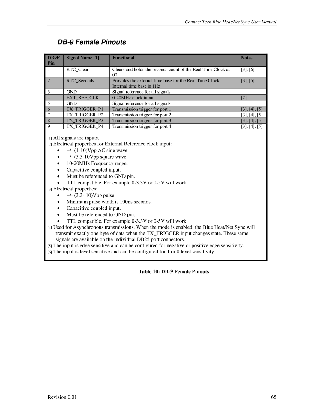
DB-9 Female Pinouts
|
| DB9F |
|
| Signal Name [1] |
|
| Functional |
|
| Notes |
|
|
|
|
|
|
|
|
|
|
|
| ||||
|
| Pin |
|
|
|
|
|
|
|
|
|
|
|
| 1 |
|
| RTC_Clear |
|
| Clears and holds the seconds count of the Real Time Clock at |
| [3], [6] |
|
| ||
|
|
|
|
|
|
| 00. |
|
|
|
|
| |
|
| 2 |
|
| RTC_Seconds |
|
| Provides the external time base for the Real Time Clock. |
|
| [3], [5] |
|
|
|
|
|
|
|
|
|
| Internal time base is 1Hz |
|
|
|
|
|
| 3 |
|
| GND |
|
| Signal reference for all signals |
|
|
|
|
| |
|
| 4 |
|
| EXT_REF_CLK |
|
|
|
| [2] |
|
| |
| 5 |
|
| GND |
|
| Signal reference for all signals |
|
|
|
|
| |
|
| 6 |
|
| TX_TRIGGER_P1 |
|
| Transmission trigger for port 1 |
|
| [3], [4], [5] |
|
|
| 7 |
|
| TX_TRIGGER_P2 |
|
| Transmission trigger for port 2 |
| [3], [4], [5] |
|
| ||
|
| 8 |
|
| TX_TRIGGER_P3 |
|
| Transmission trigger for port 3 |
|
| [3], [4], [5] |
|
|
| 9 |
|
| TX_TRIGGER_P4 |
|
| Transmission trigger for port 4 |
| [3], [4], [5] |
|
| ||
[1] All signals are inputs.
[2] Electrical properties for External Reference clock input: +/-
+/-
Must be referenced to GND pin.
TTL compatible. For example
[3] Electrical properties:
+/- (3.3- 10)Vpp pulse.
Minimum pulse width is 100ns seconds. Capacitive coupled input.
Must be referenced to GND pin.
TTL compatible. For example
[4] Used for Asynchronous transmissions. When the mode is enabled, the Blue Heat/Net Sync will transmit exactly one byte of data when the TX_TRIGGER input changes state. These same signals are available on the individual DB25 port connectors.
[5] The input is edge sensitive and can be configured for negative or positive edge sensitivity.
[6] The input is level sensitive and can be configured for 1 or 0 level sensitivity.
Table 10: DB-9 Female Pinouts
Revision 0.01 | 65 |