Connect Tech Blue Heat/Net Sync User Manual
1018 | PLD_CNTRL | R/W | D15..0 |
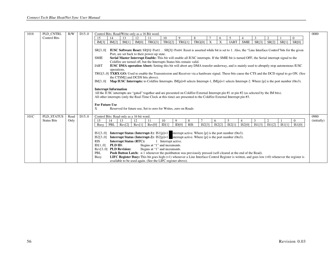
| Control Bits: Read/Write only as a 16 Bit word. |
|
|
|
|
|
|
|
|
|
|
|
|
|
|
|
|
|
|
|
|
|
|
|
|
| 0000 | |||||||||
| Control Bits |
|
|
| 15 |
| 14 |
|
| 13 |
| 12 | 11 |
|
| 10 |
|
| 9 |
|
|
| 8 |
| 7 |
| 6 |
| 5 |
| 4 | 3 | 2 | 1 | 0 |
|
|
| ||
|
|
|
|
| IM[3] | IM[2] |
| IM[1] | IM[0] | TRG[3] |
| TRG[2] | TRG[1] |
| TRG[0] | X |
| X | IABT | SMIE | SR[3] | SR[2] |
| SR[1] |
| SR[0] |
|
|
| |||||||||||
|
|
|
|
| SR[3..0] | IUSC Software Reset: SR[0]=Port1… SR[3]=Port4. Reset is asserted while bit is set to 1. Also, the “Line Interface Control”bits for the given |
| |||||||||||||||||||||||||||||||||
|
|
|
|
|
|
| Port, are set back to their |
|
|
|
|
|
|
|
|
|
|
|
|
|
|
|
|
|
|
|
|
|
|
|
| |||||||||
|
|
|
|
| SMIE | Serial Master Interrupt Enable: This bit will enable all IUSC interrupts. If the SMIE bit is turned OFF, the Serial interrupt signal to the |
| |||||||||||||||||||||||||||||||||
|
|
|
|
|
|
| Coldfire are turned off, but the Interrupts Status bits remain valid. |
|
|
|
|
|
|
|
|
|
|
|
|
|
|
|
| |||||||||||||||||
|
|
|
|
| IABT | IUSC DMA operation Abort: Setting this bit will abort any DMA transfer underway, and is mainly used to abruptly stop autonomous IUSC |
| |||||||||||||||||||||||||||||||||
|
|
|
|
|
|
| operations. |
|
|
|
|
|
|
|
|
|
|
|
|
|
|
|
|
|
|
|
|
|
|
|
|
|
|
|
|
| ||||
|
|
|
|
| TRG[3..0] TXRX GO: Used to enable the Transmission and Receiver via a hardware signal. These bits cause the CTS and the DCD signal to go ON. (See |
| ||||||||||||||||||||||||||||||||||
|
|
|
|
|
|
| the CTSM[] and DCDS bits above). |
|
|
|
|
|
|
|
|
|
|
|
|
|
|
|
|
|
|
|
|
|
|
|
|
|
| |||||||
|
|
|
|
| IM[3..0] | Map IUSC Interrupts: to Coldfire Interrupts. IM[p]=0 selects |
| |||||||||||||||||||||||||||||||||
|
|
|
|
| Interrupt Information |
|
|
|
|
|
|
|
|
|
|
|
|
|
|
|
|
|
|
|
|
|
|
|
|
|
|
|
|
| ||||||
|
|
|
|
| All the IUSC interrupts are “gated” together and are presented on Coldfire External Interrupt pin #1 or pin #2 (as selected by the IM bits). |
|
|
|
|
| ||||||||||||||||||||||||||||||
|
|
|
|
| All other interrupts (only the |
|
|
|
|
|
|
|
|
| ||||||||||||||||||||||||||
|
|
|
|
| For Future Use |
|
|
|
|
|
|
|
|
|
|
|
|
|
|
|
|
|
|
|
|
|
|
|
|
|
|
|
|
|
|
|
| |||
|
|
|
|
| X | Reserved for future use, Set to zero for Writes, zero on Reads |
|
|
|
|
|
|
|
|
|
|
|
|
|
|
|
|
|
| ||||||||||||||||
|
|
|
|
|
|
|
|
|
|
|
|
|
|
|
|
|
|
|
|
|
|
|
|
|
|
|
|
|
|
|
| |||||||||
101C | PLD_STATUS | Read | D15..0 |
| Control Bits: Read only as a 16 bit word. |
|
|
|
|
|
|
|
|
|
|
|
|
|
|
|
|
|
|
|
|
|
|
|
|
| 0900 | |||||||||
| Status Bits | Only |
|
| 15 |
| 14 |
| 13 |
| 12 | 11 |
| 10 |
| 9 |
| 8 |
|
| 7 |
| 6 |
|
| 5 |
| 4 | 3 | 2 |
| 1 |
| 0 |
|
| (initially) | |||
|
|
|
|
| Busy |
| PBL | Rev[2] | Rev[1] | Rev[0] | ID[1] |
| ID[0] |
| RIS |
| IS2[3] | IS2[2] |
| IS2[1] |
| IS2[0] | IS1[3] | IS1[2] |
| IS1[1] |
| IS1[0] |
|
| ||||||||||
|
|
|
|
| IS1[3..0] | Interrupt Status | Interrupt active. Where [p] is the port number (0to3). |
|
|
|
|
|
|
|
|
| ||||||||||||||||||||||||
|
|
|
|
| IS2[3..0] | Interrupt Status | Interrupt active. Where [p] is the port number (0to3). |
|
|
|
|
|
|
|
|
| ||||||||||||||||||||||||
|
|
|
|
| RIS | Interrupt Status (RTC): | 1 |
| Interrupt active. |
|
|
|
|
|
|
|
|
|
|
|
|
|
|
|
|
|
|
|
| |||||||||||
|
|
|
|
| ID[1..0] | PLD ID: | Begins at “1” and increments. |
|
|
|
|
|
|
|
|
|
|
|
|
|
|
|
|
|
|
|
| |||||||||||||
|
|
|
|
| Rev[3..0] | PLD Revision: | Begins at “1” and increments. |
|
|
|
|
|
|
|
|
|
|
|
|
|
|
|
|
|
|
|
| |||||||||||||
|
|
|
|
| PBL | Push Button Latch: = 1 whenever the pushbutton was previously pressed |
|
|
|
|
|
|
|
| ||||||||||||||||||||||||||
|
|
|
|
| Busy | LIFC Register Busy: This bit goes high (=1) whenever a Line Interface Control Register is written, and goes low (=0) whenever the register is |
| |||||||||||||||||||||||||||||||||
|
|
|
|
|
|
| available to be used again. (See the LIFC register above). |
|
|
|
|
|
|
|
|
|
|
|
|
|
|
|
|
|
|
|
| |||||||||||||
56 | Revision 0.03 |