7.5 Mounting and attaching the GPS antenna
The GPS antenna used with the
The GPS antenna connector is a standard MCX type that requires the GPS antenna cable to use a MCX plug connector. The
7.6 Connecting to the I/O Port
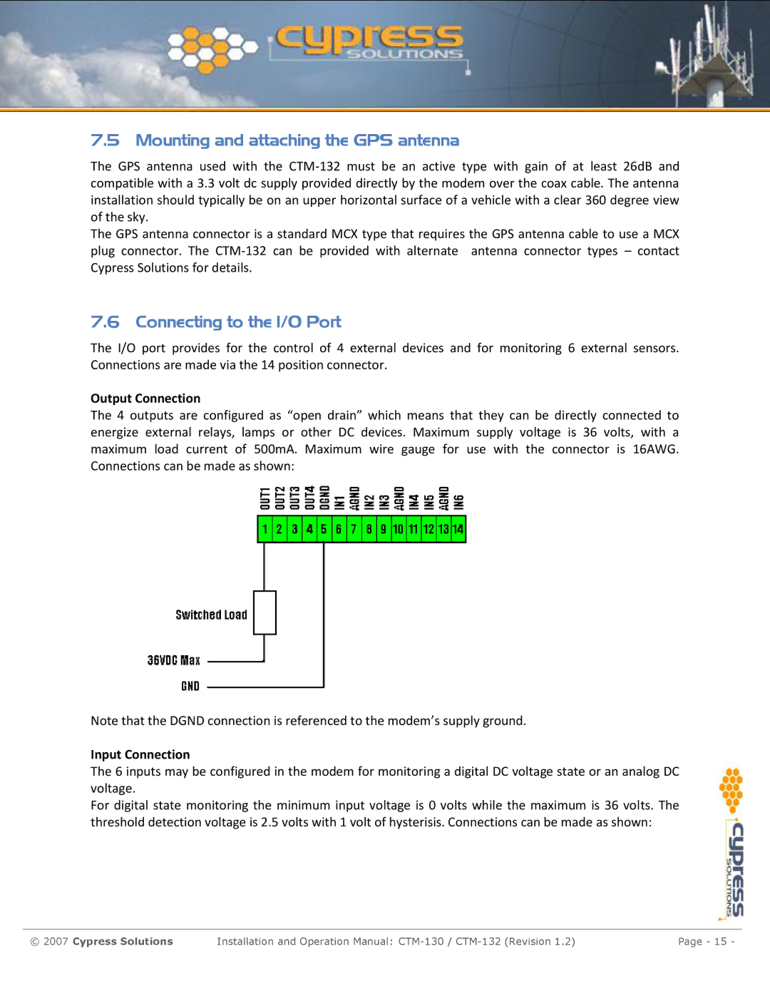
The I/O port provides for the control of 4 external devices and for monitoring 6 external sensors. Connections are made via the 14 position connector.
Output Connection
The 4 outputs are configured as “open drain” which means that they can be directly connected to energize external relays, lamps or other DC devices. Maximum supply voltage is 36 volts, with a maximum load current of 500mA. Maximum wire gauge for use with the connector is 16AWG. Connections can be made as shown:
Note that the DGND connection is referenced to the modem’s supply ground.
Input Connection
The 6 inputs may be configured in the modem for monitoring a digital DC voltage state or an analog DC voltage.
For digital state monitoring the minimum input voltage is 0 volts while the maximum is 36 volts. The threshold detection voltage is 2.5 volts with 1 volt of hysterisis. Connections can be made as shown:
© 2007 Cypress Solutions | Installation and Operation Manual: | Page - 15 - |
