CY7C64215
Each user module establishes the basic register settings that implement the selected function. It also provides parameters that allow you to tailor its precise configuration to your particular application. For example, a Pulse Width Modulator User Module configures one or more digital PSoC blocks, one for each 8 bits of resolution. The user module parameters permit the designer to establish the pulse width and duty cycle. User modules also provide tested software to cut development time. The user module application programming interface (API) provides
The API functions are documented in user module data sheets that are viewed directly in the PSoC Designer IDE. These data sheets explain the internal operation of the user module and provide performance specifications. Each data sheet describes the use of each user module parameter and documents the setting of each register controlled by the user module.
The development process starts when you open a new project and bring up the Device Editor/Chip Layout View, a graphical user interface (GUI) for configuring the hardware. You pick the user modules you need for your project and map them onto the PSoC blocks with
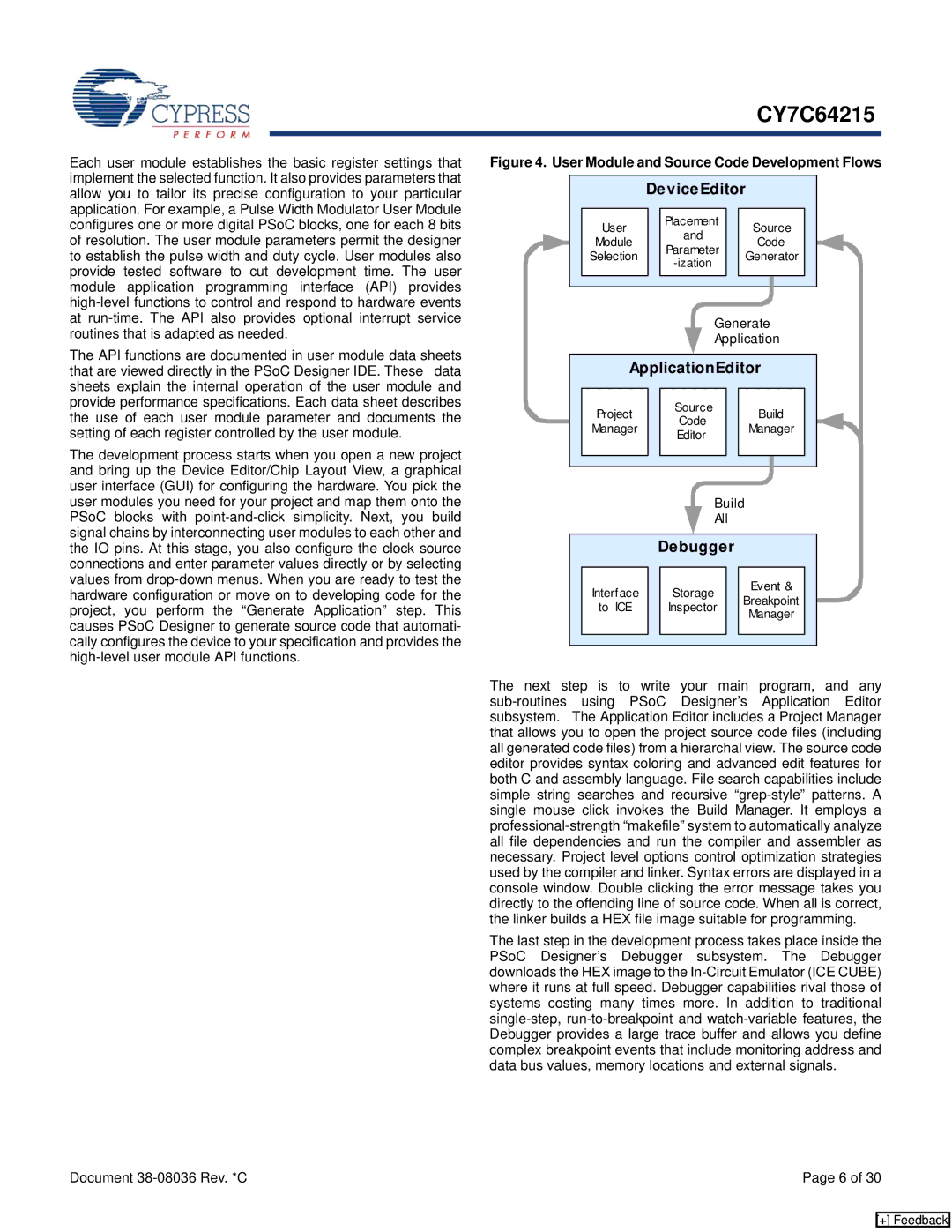
Figure 4. User Module and Source Code Development Flows
|
|
| DeviceEditor |
|
|
|
|
| ||||||
|
|
|
|
|
|
|
|
|
|
|
|
|
| |
|
| User |
|
| Placement |
|
| Source |
|
| ||||
|
|
|
| and |
|
|
|
| ||||||
|
| Module |
|
|
|
| Code |
|
| |||||
|
|
|
| Parameter |
|
|
|
| ||||||
|
| Selection |
|
|
| Generator |
|
| ||||||
|
|
|
|
|
|
| ||||||||
|
|
|
|
|
|
|
|
|
|
|
| |||
|
|
|
|
|
|
|
|
|
|
|
|
| ||
|
|
|
|
|
|
|
|
|
|
|
|
|
|
|
|
|
|
|
|
|
|
|
|
| |||||
|
|
|
|
|
|
|
|
|
| |||||
|
|
|
|
|
|
| Generate |
| ||||||
|
|
|
|
|
|
|
| |||||||
|
|
|
|
|
|
| Application |
| ||||||
|
|
|
|
|
|
|
|
|
|
|
| |||
|
| ApplicationEditor |
| |||||||||||
|
|
|
|
|
|
|
|
|
|
|
|
|
|
|
|
| Project |
|
| Source |
|
| Build |
|
| ||||
|
|
|
| Code |
|
|
|
| ||||||
|
| Manager |
|
|
|
| Manager |
|
| |||||
|
|
|
| Editor |
|
|
|
| ||||||
|
|
|
|
|
|
|
|
|
|
|
| |||
|
|
|
|
|
|
|
|
|
|
|
|
|
|
|
|
|
|
|
|
|
|
|
|
|
|
|
|
|
|
|
|
|
|
|
|
|
|
|
|
|
|
| ||
|
|
|
|
|
|
| Build |
|
|
|
|
| ||
|
|
|
|
|
|
|
|
|
|
|
| |||
|
|
|
|
|
|
| All |
|
|
|
|
|
| |
|
|
|
|
|
|
|
|
|
|
|
|
|
|
|
|
|
|
| Debugger |
|
|
|
|
|
| ||||
|
|
|
|
|
|
|
|
|
|
|
|
|
|
|
|
| Interface |
|
| Storage |
|
| Event & |
|
| ||||
|
|
|
|
| Breakpoint |
|
| |||||||
|
| to ICE |
|
| Inspector |
|
|
| ||||||
|
|
|
|
|
| Manager |
|
| ||||||
|
|
|
|
|
|
|
|
|
|
|
| |||
|
|
|
|
|
|
|
|
|
|
|
|
|
|
|
|
|
|
|
|
|
|
|
|
|
|
|
|
|
|
The next step is to write your main program, and any
The last step in the development process takes place inside the PSoC Designer’s Debugger subsystem. The Debugger downloads the HEX image to the
Document | Page 6 of 30 |
[+] Feedback