Manuals
/
D-Link
/
Computer Equipment
/
Switch
D-Link
DKVM-IP1
manual
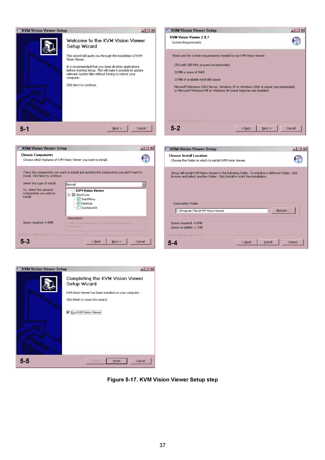
KVM Vision Viewer Setup step
Models:
DKVM-IP1
1
40
73
73
Download
73 pages
5.65 Kb
37
38
39
40
41
42
43
44
Troubleshooting
Install
Cable diagrams PS/2 Cable
Password
Initial IP configuration
Reset Functions
Exclusive Access
DKVM-IP1 switch Setup Tool
Remote Mouse Settings
How to
Page 40
Image 40
5-1
5-2
5-3
5-4
5-5
Figure
5-17.
KVM Vision Viewer Setup step
37
Page 39
Page 41
Page 40
Image 40
Page 39
Page 41
Contents
Link DKVM-IP1 Port KVM Switch Over IP Manual
Contents
Menu Options
DKVM-IP1 switch hardware installation
Installation
Video modes
Initial IP configuration
Web interface
Remote Console
Top part of the Remote Console
When the server is up and running
When the server is dead
Features
Package contents
Technical specifications Model No
DKVM-IP1 1port KVM Switch Over IP
System requirement
Description
VGA Cable
Cable diagrams PS/2 Cable
USB 2.0 Cable
Operation Overview
Connecting DKVM-IP1 switch to the host system
Step
Connect the monitor to the DKVM-IP1 switch console side
Option
Ethernet connection
Page
Initial configuration via Dhcp server
Initial Configuration
DKVM-IP1 switch Setup Tool
Authentication
Initial configuration via serial console
IP auto configuration
Keyboard, Mouse and Video configuration
DKVM-IP1 switch keyboard settings
IP address
Remote Mouse Settings
Host system mouse settings
Auto mouse speed and mouse synchronization
Fast Sync
Windows XP Mouse Settings
Single and Double Mouse Mode
Recommended Mouse Settings
Special Mouse Driver
Prerequisites
Telnet
Login into the DKVM-IP1 switch and logout
Internet Explorer displaying the encryption key length
Navigation
Main
Logout from the DKVM-IP1 switch
Remote Console General description
Main Window
Remote Console Control Bar
Exclusive Access
Remote Console Options Menu
Mouse Handling
Scaling
Local Cursor
Video Settings
Remote Console Options MenuCursor
Soft Keyboard
12. Soft Keyboard
Hotkeys
Local Keyboard
Encoding
Remote Console Status Line
15. Encoding
17. Status line transfer rate
Remote KVM Console
Telnet Console
Help
Cls
Quit
Version
Upload a Floppy Image
Use Image on Windows Share Samba
Selecting CD ROM
Select Sharing to open the configuration dialog
Creating an Image Floppy Images
CD ROM/ISO Images
Dd if=/dev/cdrom of=/tmp/cdrom.image
Driver Installation
Drive redirection
17. KVM Vision Viewer Setup step
Create a New Device
17. Create a new Device
Drive Redirection Settings
18. New Device
Options
Change Password
Users
Settings
User Console
14. User Console Settings Part
15. User Console Settings Part
17. Keyboard and Mouse Settings
Keyboard/Mouse
Page
Video
Network
19. Network Settings Part
19. Network Settings Part
Dynamic DNS
20. Dynamic DNS
Page
Security
22. Device Security
23. Certificate Settings
Certificate
24. SSL Certificate Upload
Serial Port
25. Serial Port
Page
Date And Time
Event Log
Page
Page
Device Status
Board Summary
Update Firmware
Reset Functions
Even log
Page
Unit Reset
35 Unit Reset
Troubleshooting
Certificates
CE Certificate
Pin Assignments
Key Codes
F12 Printscreen Scroll Lock Break Insert Home Delete
Video Modes
Rack mount kit installation diagram
Top
Page
Image
Contents