INSTALLATION
GAS HOOK-UP
Connection: 1/2” NPT male with a 3/8” Flare adapter (included). LP Hose with a quick disconnect and fittings are
included. Operating pressure: 11.0” W.C.
Note: All gas piping and connectors must conform to the Standard for Connectors for Outdoor Gas Appliances and Manufactured Homes, ANSI Z21.75/CSA 6.27.
CAUTION!
Before connecting LP tank to regulator, check that all grill burners and side burners, smokers, and rotisserie valves are in the OFF position and open grill lid.
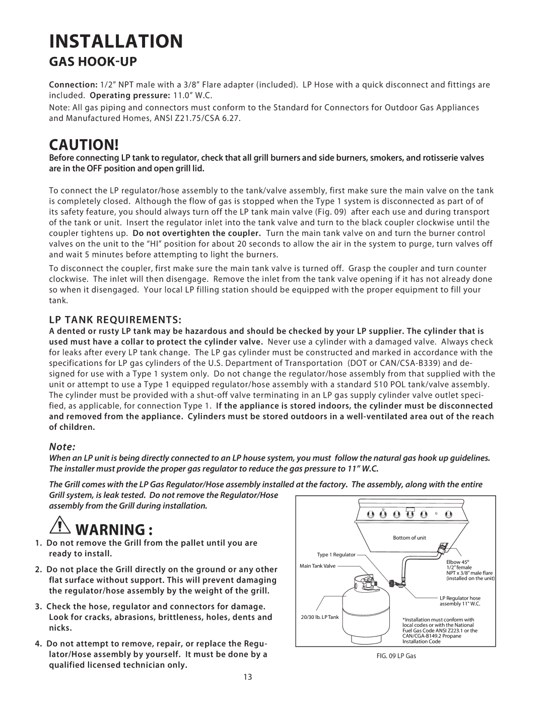
To connect the LP regulator/hose assembly to the tank/valve assembly, first make sure the main valve on the tank is completely closed. Although the flow of gas is stopped when the Type 1 system is disconnected as part of of its safety feature, you should always turn off the LP tank main valve (Fig. 09) after each use and during transport of the tank or unit. Insert the regulator inlet into the tank valve and turn to the black coupler clockwise until the coupler tightens up. Do not overtighten the coupler. Turn the main tank valve on and turn the burner control valves on the unit to the “HI” position for about 20 seconds to allow the air in the system to purge, turn valves off and wait 5 minutes before attempting to light the burners.
To disconnect the coupler, first make sure the main tank valve is turned off. Grasp the coupler and turn counter clockwise. The inlet will then disengage. Remove the inlet from the tank valve opening if it has not already done so when it disengaged. Your local LP filling station should be equipped with the proper equipment to fill your tank.
LP TANK REQUIREMENTS:
A dented or rusty LP tank may be hazardous and should be checked by your LP supplier. The cylinder that is used must have a collar to protect the cylinder valve. Never use a cylinder with a damaged valve. Always check for leaks after every LP tank change. The LP gas cylinder must be constructed and marked in accordance with the specifications for LP gas cylinders of the U.S. Department of Transportation (DOT or
Note:
When an LP unit is being directly connected to an LP house system, you must follow the natural gas hook up guidelines. The installer must provide the proper gas regulator to reduce the gas pressure to 11” W.C.
The Grill comes with the LP Gas Regulator/Hose assembly installed at the factory. The assembly, along with the entire Grill system, is leak tested. Do not remove the Regulator/Hose
assembly from the Grill during installation.
WARNING : |
| Bottom of unit | |
1. Do not remove the Grill from the pallet until you are |
| ||
|
| ||
ready to install. | Type 1 Regulator | Elbow 45º | |
2. Do not place the Grill directly on the ground or any other | Main Tank Valve | ||
1/2” female | |||
| NPT x 3/8” male flare | ||
flat surface without support. This will prevent damaging |
| (installed on the unit) | |
|
| ||
the regulator/hose assembly by the weight of the grill. |
| LP Regulator hose | |
|
| ||
3. Check the hose, regulator and connectors for damage. |
| assembly 11" W.C. | |
|
| ||
Look for cracks, abrasions, brittleness, holes, dents and | 20/30 lb. LP Tank | *Installation must conform with | |
nicks. |
| local codes or with the National | |
| Fuel Gas Code ANSI Z223.1 or the | ||
4. Do not attempt to remove, repair, or replace the Regu- |
| ||
| Installation Code | ||
|
| ||
lator/Hose assembly by yourself. It must be done by a |
| FIG. 09 LP Gas | |
qualified licensed technician only. |
|
|
13