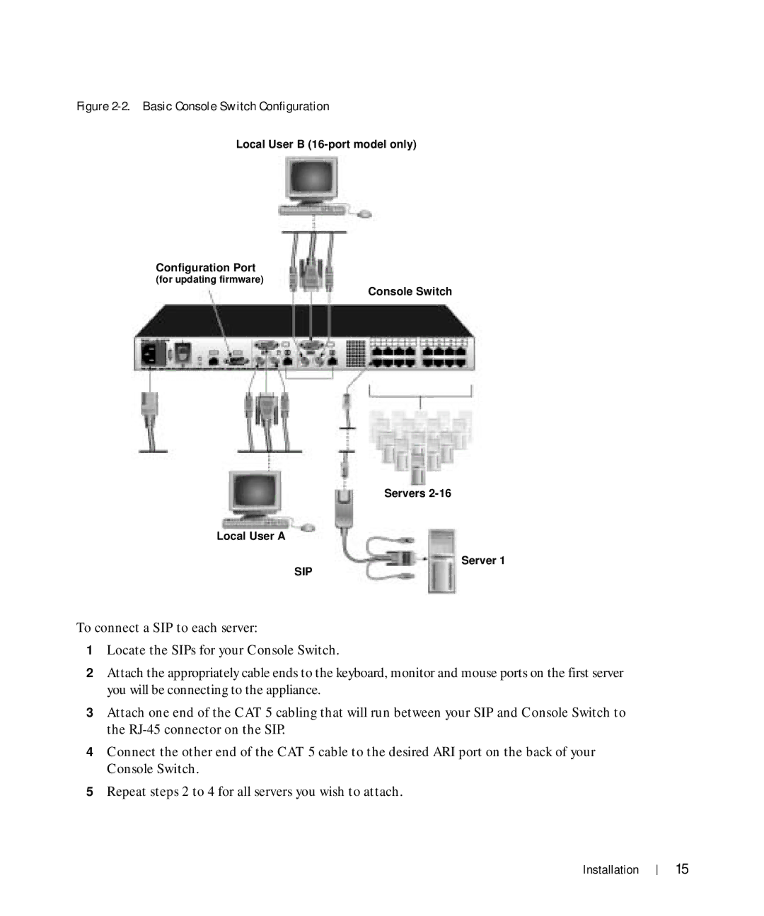
Figure 2-2. Basic Console Switch Configuration
Local User B
Configuration Port
(for updating firmware)
Console Switch
Servers
Local User A
Server 1
SIP
To connect a SIP to each server:
1Locate the SIPs for your Console Switch.
2Attach the appropriately cable ends to the keyboard, monitor and mouse ports on the first server you will be connecting to the appliance.
3Attach one end of the CAT 5 cabling that will run between your SIP and Console Switch to the
4Connect the other end of the CAT 5 cable to the desired ARI port on the back of your Console Switch.
5Repeat steps 2 to 4 for all servers you wish to attach.
Installation
15