w w w . d e l l . c o m s u p p o r t . d e l l . c o m
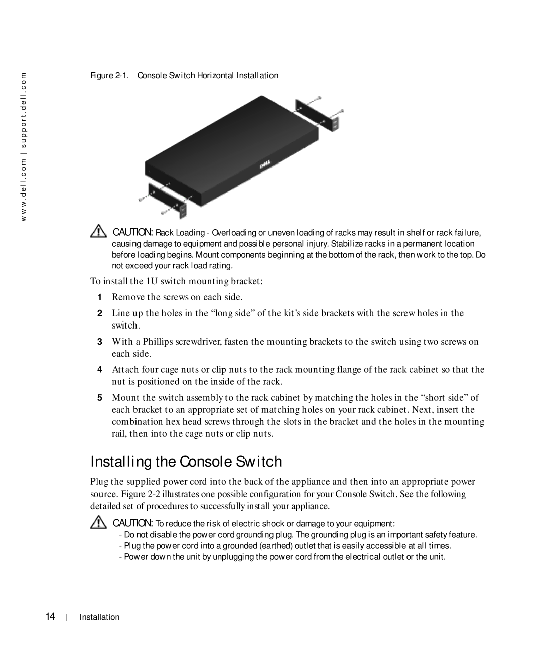
Figure 2-1. Console Switch Horizontal Installation
CAUTION: Rack Loading - Overloading or uneven loading of racks may result in shelf or rack failure, causing damage to equipment and possible personal injury. Stabilize racks in a permanent location before loading begins. Mount components beginning at the bottom of the rack, then work to the top. Do not exceed your rack load rating.
To install the 1U switch mounting bracket:
1Remove the screws on each side.
2Line up the holes in the “long side” of the kit’s side brackets with the screw holes in the switch.
3With a Phillips screwdriver, fasten the mounting brackets to the switch using two screws on each side.
4Attach four cage nuts or clip nuts to the rack mounting flange of the rack cabinet so that the nut is positioned on the inside of the rack.
5Mount the switch assembly to the rack cabinet by matching the holes in the “short side” of each bracket to an appropriate set of matching holes on your rack cabinet. Next, insert the combination hex head screws through the slots in the bracket and the holes in the mounting rail, then into the cage nuts or clip nuts.
Installing the Console Switch
Plug the supplied power cord into the back of the appliance and then into an appropriate power source. Figure
CAUTION: To reduce the risk of electric shock or damage to your equipment:
-Do not disable the power cord grounding plug. The grounding plug is an important safety feature.
-Plug the power cord into a grounded (earthed) outlet that is easily accessible at all times.
-Power down the unit by unplugging the power cord from the electrical outlet or the unit.
14
Installation