PMAC2A PC104 Hardware Reference Manual
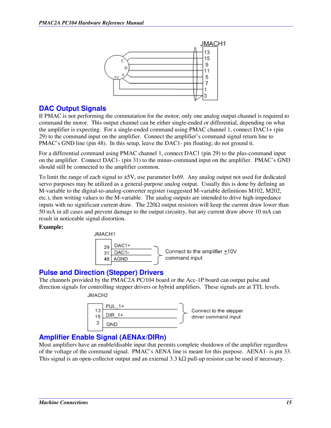
DAC Output Signals
If PMAC is not performing the commutation for the motor, only one analog output channel is required to command the motor. This output channel can be either single-ended or differential, depending on what the amplifier is expecting. For a single-ended command using PMAC channel 1, connect DAC1+ (pin
29)to the command input on the amplifier. Connect the amplifier’s command signal return line to PMAC’s GND line (pin 48). In this setup, leave the DAC1- pin floating; do not ground it.
For a differential command using PMAC channel 1, connect DAC1 (pin 29) to the plus-command input on the amplifier. Connect DAC1- (pin 31) to the minus-command input on the amplifier. PMAC’s GND should still be connected to the amplifier common.
To limit the range of each signal to ±5V, use parameter Ix69. Any analog output not used for dedicated servo purposes may be utilized as a general-purpose analog output. Usually this is done by defining an M-variable to the digital-to-analog-converter register (suggested M-variable definitions M102, M202, etc.), then writing values to the M-variable. The analog outputs are intended to drive high-impedance inputs with no significant current draw. The 220Ω output resistors will keep the current draw lower than 50 mA in all cases and prevent damage to the output circuitry, but any current draw above 10 mA can result in noticeable signal distortion.
Example:
Pulse and Direction (Stepper) Drivers
The channels provided by the PMAC2A PC/104 board or the Acc-1P board can output pulse and direction signals for controlling stepper drivers or hybrid amplifiers. These signals are at TTL levels.
Amplifier Enable Signal (AENAx/DIRn)
Most amplifiers have an enable/disable input that permits complete shutdown of the amplifier regardless of the voltage of the command signal. PMAC’s AENA line is meant for this purpose. AENA1- is pin 33. This signal is an open-collector output and an external 3.3 kΩ pull-up resistor can be used if necessary.