PMAC2A PC104 Hardware Reference Manual
BASE BOARD E-POINT JUMPER DESCRIPTIONS
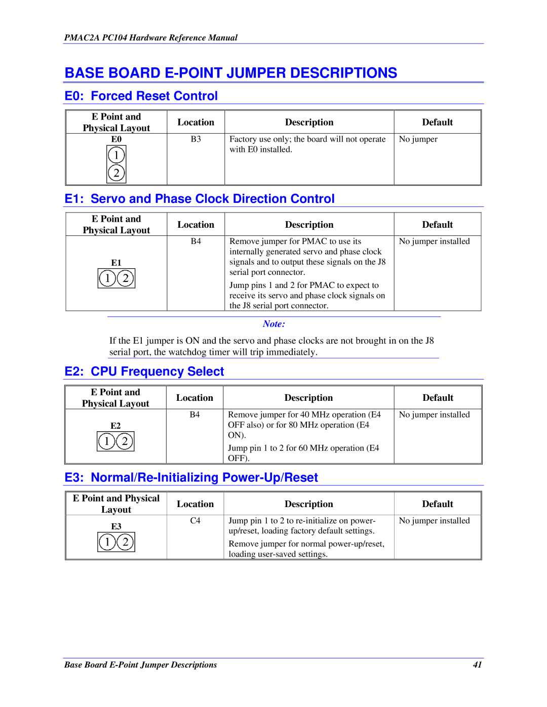
E0: Forced Reset Control
E Point and | Location | Description | Default | |
Physical Layout | ||||
|
|
| ||
E0 | B3 | Factory use only; the board will not operate | No jumper | |
|
| with E0 installed. |
| |
|
|
|
|
E1: Servo and Phase Clock Direction Control
E Point and | Location | Description | Default | |
Physical Layout | ||||
|
|
| ||
| B4 | Remove jumper for PMAC to use its | No jumper installed | |
|
| internally generated servo and phase clock |
| |
E1 |
| signals and to output these signals on the J8 |
| |
|
| serial port connector. |
| |
|
| Jump pins 1 and 2 for PMAC to expect to |
| |
|
| receive its servo and phase clock signals on |
| |
|
| the J8 serial port connector. |
|
Note:
If the E1 jumper is ON and the servo and phase clocks are not brought in on the J8 serial port, the watchdog timer will trip immediately.
E2: CPU Frequency Select
| E Point and | Location | Description | Default |
|
| Physical Layout |
| |||
|
|
|
|
| |
|
| B4 | Remove jumper for 40 MHz operation (E4 | No jumper installed |
|
| E2 |
| OFF also) or for 80 MHz operation (E4 |
|
|
|
|
| ON). |
|
|
|
|
| Jump pin 1 to 2 for 60 MHz operation (E4 |
|
|
|
|
| OFF). |
|
|
| E3: |
|
| ||
|
|
|
|
|
|
| E Point and Physical | Location | Description | Default |
|
| Layout |
| |||
|
|
|
|
| |
| E3 | C4 | Jump pin 1 to 2 to | No jumper installed |
|
|
| up/reset, loading factory default settings. |
|
| |
|
|
|
|
| |
|
|
| Remove jumper for normal |
|
|
|
|
| loading |
|
|
Base Board | 41 |
