PMAC2A PC104 Hardware Reference Manual
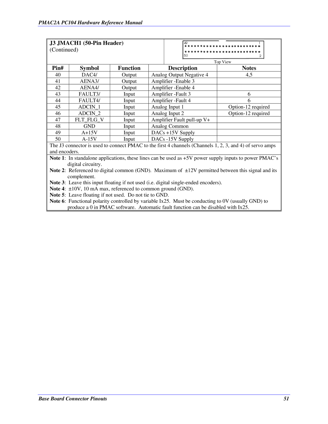
J3 JMACH1 (50-Pin Header) (Continued)
Top View
Pin# | Symbol | Function | Description | Notes |
40 | DAC4/ | Output | Analog Output Negative 4 | 4,5 |
41 | AENA3/ | Output | Amplifier |
|
42 | AENA4/ | Output | Amplifier |
|
43 | FAULT3/ | Input | Amplifier | 6 |
44 | FAULT4/ | Input | Amplifier | 6 |
45 | ADCIN_1 | Input | Analog Input 1 | |
46 | ADCIN_2 | Input | Analog Input 2 | |
47 | FLT_FLG_V | Input | Amplifier Fault |
|
48 | GND | Input | Analog Common |
|
49 | A+15V | Input | DACs +15V Supply |
|
50 | Input | DACs |
|
The J3 connector is used to connect PMAC to the first 4 channels (Channels 1, 2, 3, and 4) of servo amps and encoders.
Note 1: In standalone applications, these lines can be used as +5V power supply inputs to power PMAC’s digital circuitry.
Note 2: Referenced to digital common (GND). Maximum of ±12V permitted between this signal and its complement.
Note 3: Leave this input floating if not used (i.e. digital
Note 4: ±10V, 10 mA max, referenced to common ground (GND).
Note 5: Leave floating if not used. Do not tie to GND.
Note 6: Functional polarity controlled by variable Ix25. Must be conducting to 0V (usually GND) to
produce a 0 in PMAC software. Automatic fault function can be disabled with Ix25.
Base Board Connector Pinouts | 51 |