PMAC2A PC104 Hardware Reference Manual
BASE BOARD CONNECTOR PINOUTS
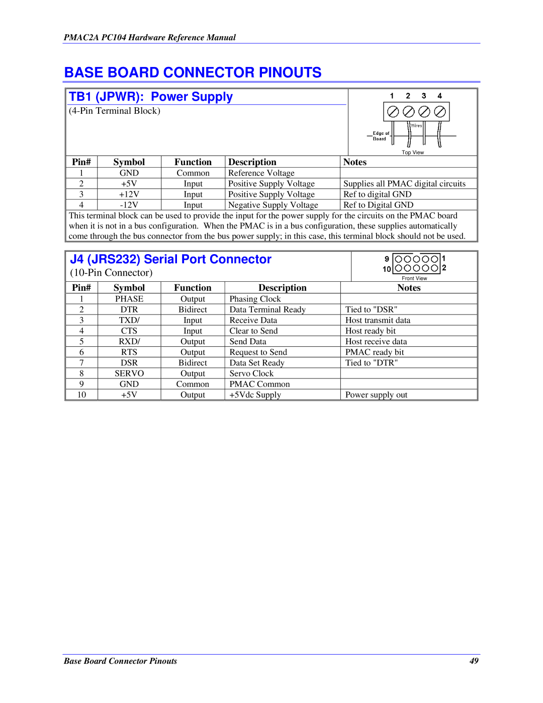
TB1 (JPWR): Power Supply
Top View
Pin# | Symbol | Function | Description | Notes |
1 | GND | Common | Reference Voltage |
|
2 | +5V | Input | Positive Supply Voltage | Supplies all PMAC digital circuits |
3 | +12V | Input | Positive Supply Voltage | Ref to digital GND |
4 | Input | Negative Supply Voltage | Ref to Digital GND |
This terminal block can be used to provide the input for the power supply for the circuits on the PMAC board when it is not in a bus configuration. When the PMAC is in a bus configuration, these supplies automatically come through the bus connector from the bus power supply; in this case, this terminal block should not be used.
J4 (JRS232) Serial Port Connector
(10-Pin Connector)
Front View
Pin# | Symbol | Function | Description | Notes |
1 | PHASE | Output | Phasing Clock |
|
2 | DTR | Bidirect | Data Terminal Ready | Tied to "DSR" |
3 | TXD/ | Input | Receive Data | Host transmit data |
4 | CTS | Input | Clear to Send | Host ready bit |
5 | RXD/ | Output | Send Data | Host receive data |
6 | RTS | Output | Request to Send | PMAC ready bit |
7 | DSR | Bidirect | Data Set Ready | Tied to "DTR" |
8 | SERVO | Output | Servo Clock |
|
9 | GND | Common | PMAC Common |
|
10 | +5V | Output | +5Vdc Supply | Power supply out |
Base Board Connector Pinouts | 49 |