PMAC2A PC104 Hardware Reference Manual
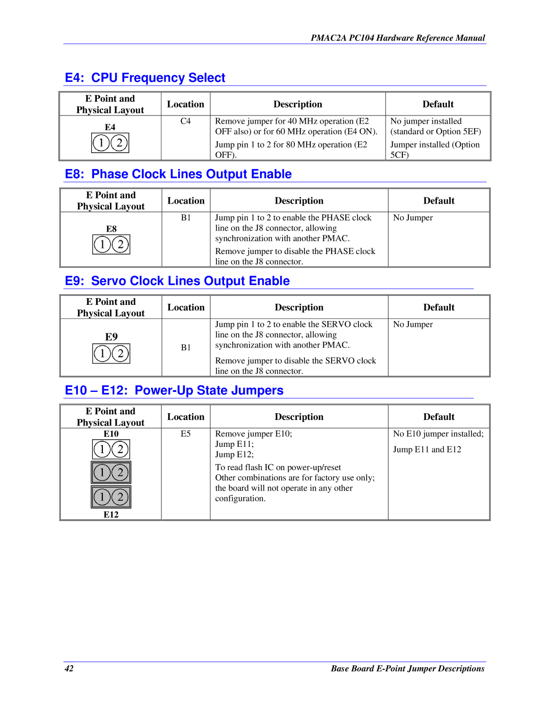
E4: CPU Frequency Select
| E Point and | Location | Description |
| Default | ||
| Physical Layout |
| |||||
|
|
|
|
|
|
| |
| E4 | C4 | Remove jumper for 40 MHz operation (E2 |
| No jumper installed | ||
|
| OFF also) or for 60 MHz operation (E4 ON). |
| (standard or Option 5EF) | |||
|
|
|
| ||||
|
|
| Jump pin 1 to 2 for 80 MHz operation (E2 |
| Jumper installed (Option | ||
|
|
| OFF). |
| 5CF) | ||
| E8: Phase Clock Lines Output Enable |
|
|
|
| ||
|
|
|
|
|
|
|
|
| E Point and | Location | Description |
| Default | ||
| Physical Layout |
| |||||
|
|
|
|
|
|
| |
|
| B1 | Jump pin 1 to 2 to enable the PHASE clock |
| No Jumper | ||
| E8 |
| line on the J8 connector, allowing |
|
|
|
|
|
|
| synchronization with another PMAC. |
|
|
|
|
|
|
| Remove jumper to disable the PHASE clock |
|
|
|
|
|
|
| line on the J8 connector. |
|
|
|
|
| E9: Servo Clock Lines Output Enable |
|
|
|
| ||
|
|
|
|
|
|
|
|
| E Point and | Location | Description |
| Default | ||
| Physical Layout |
| |||||
|
|
|
|
|
|
| |
|
|
| Jump pin 1 to 2 to enable the SERVO clock |
| No Jumper | ||
| E9 |
| line on the J8 connector, allowing |
|
|
|
|
|
| B1 | synchronization with another PMAC. |
|
|
|
|
|
|
| Remove jumper to disable the SERVO clock |
|
|
|
|
|
|
| line on the J8 connector. |
|
|
|
|
| E10 – E12: |
|
|
|
| ||
|
|
|
|
|
|
|
|
| E Point and | Location | Description |
| Default | ||
| Physical Layout |
| |||||
|
|
|
|
|
|
| |
| E10 | E5 | Remove jumper E10; |
| No E10 jumper installed; | ||
|
|
| Jump E11; |
| Jump E11 and E12 | ||
|
|
| Jump E12; |
| |||
|
|
|
|
|
|
| |
|
|
| To read flash IC on |
|
|
|
|
|
|
| Other combinations are for factory use only; |
|
|
|
|
|
|
| the board will not operate in any other |
|
|
|
|
|
|
| configuration. |
|
|
|
|
| E12 |
|
|
|
|
|
|
42 | Base Board |
